Method for implementing low-frequency rotating constant high magnetic field

a high magnetic field, low-frequency rotating technology, applied in the field of magnetic therapy, can solve the problems of undesirable magnetic therapy effect, waste of energy, etc., and achieve the effect of reducing the leakage of magnetic lines of force and maximum magnetic field intensity

Inactive Publication Date: 2014-09-09
SHENZHEN HENG AN HONG YUAN MAG TECH
View PDF11 Cites 0 Cited by
  • Summary
  • Abstract
  • Description
  • Claims
  • Application Information

AI Technical Summary

Benefits of technology

[0005]In view of the defects in the prior art that the magnetic therapy instruments adopt an open magnetic field, which easily causes leakage of magnetic lines of force and leads to an undesirable magnetic therapy effect, the present invention provides a method for implementing a low-frequency rotating constant high magnetic field. The method adopts an even number of high field magnets, in which the high field magnets are fixedly mounted on a magnetically permeable rotating arm, a cross section of the high field magnet is in a geometric shape without edges or corners, thereby greatly reducing the leakage of magnetic lines of force around the high field magnet and the amount of magnets. The area of a connecting surface of the high field magnet connected to the magnetically permeable rotating arm is smaller than that of a free surface symmetrical to the connecting surface, thereby ensuring that magnetic lines of force emerge from a free surface of one high field magnet and returns from a free surface of another high field magnet. As the magnetic lines of force inside the magnet enter from one magnet to another magnet through the magnetically permeable rotating arm, no leakage occurs, so that the magnetic lines of force are concentrated, and maximum magnetic field intensity is achieved. A rotating apparatus is used to drive the magnetically permeable rotating arm and the high field magnets to rotate, thereby achieving the objective of low-frequency high magnetic field therapy.
[0015]The beneficial effect of the present invention is that, the present invention adopts the high field magnet of a special shape as a magnetic therapy apparatus, in which the cross section of the high field magnet has no edge or corner, which reduces the magnetic leakage around the magnet, so that the magnet lines of force are concentrated and emerge upward, thereby reducing magnetic leakage in other directions, increasing the intensity of the magnetic field in a useful direction, effectively preventing interference on other electrical appliances, and greatly reducing the amount of magnets. The present invention adopts the conical magnet, and the area of an upward surface (that is, the free surface) is larger than that of a downward surface (that is, the connecting surface), so that according to an edge effect of the magnetic field, the upward emerging height of the magnetic lines of force is greater, and the magnetic flux density is greater, thereby achieving a better magnetic therapy effect.

Problems solved by technology

However, all of the above patents have defects, and in view of the defects, the applicant has provided a high magnetic field therapy apparatus, referring to the invention patent (Patent No. 93114013,1) entitled “High Magnetic Field Therapeutic Apparatus Using Low-frequency Rotating Permanent Magnet” which was applied by the applicant previously.
In one aspect, the open magnetic field inevitably causes leakage of magnetic lines of force, and the leaked magnetic lines of force fail to contribute to the magnetic therapy and are wasted.
In addition, the leakage of the magnetic lines of force affects adjacent devices, for example, mobile phones, televisions and radios.
In another aspect, the magnetic lines of force of the open magnetic field are scattered, the intensity of the magnetic field is low, and the penetration distance of the magnetic lines of force is short, leading to an undesirable magnetic therapy effect.

Method used


Image

  • Method for implementing low-frequency rotating constant high magnetic field
  • Method for implementing low-frequency rotating constant high magnetic field
  • Method for implementing low-frequency rotating constant high magnetic field

Examples


embodiment 1

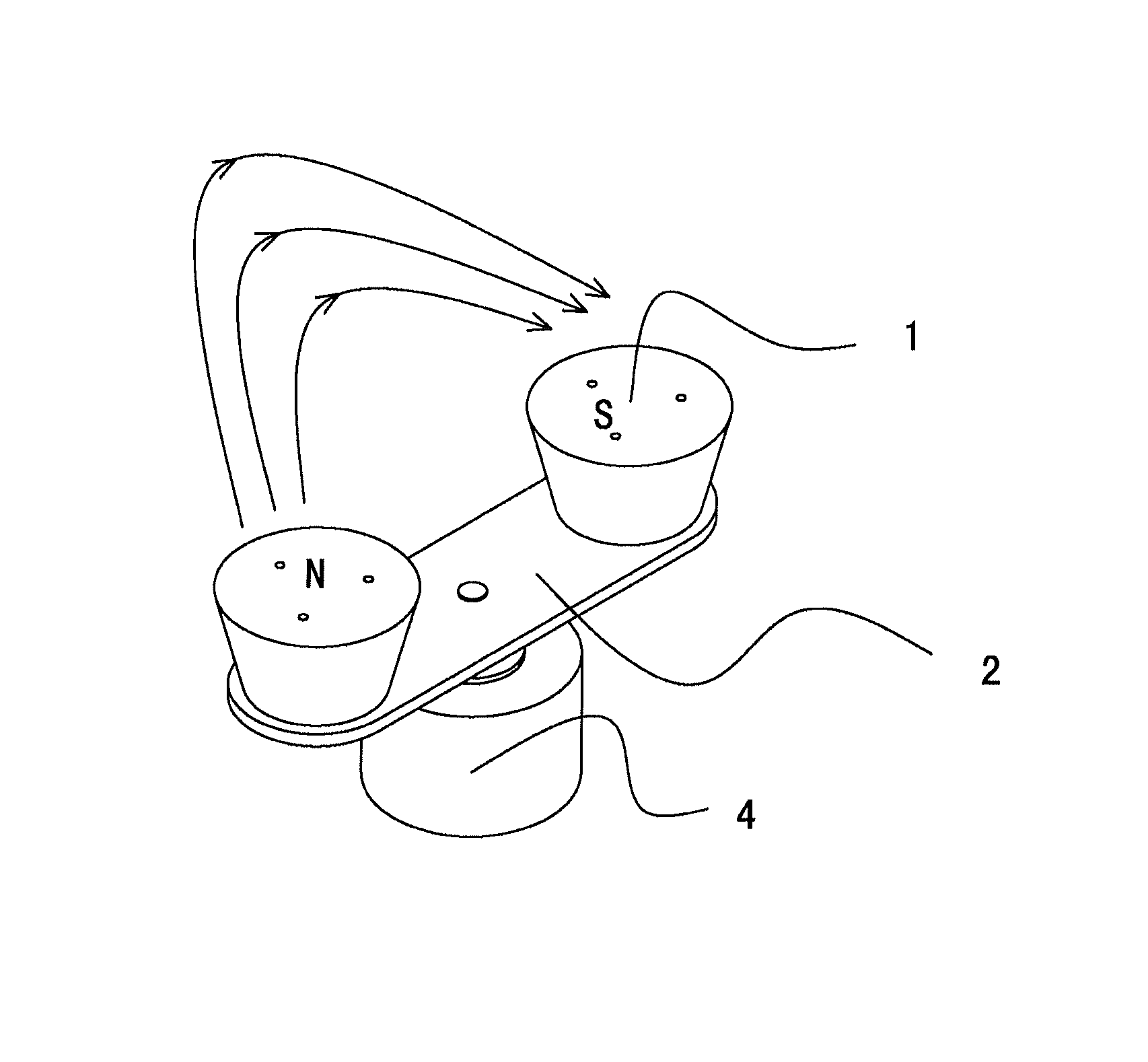
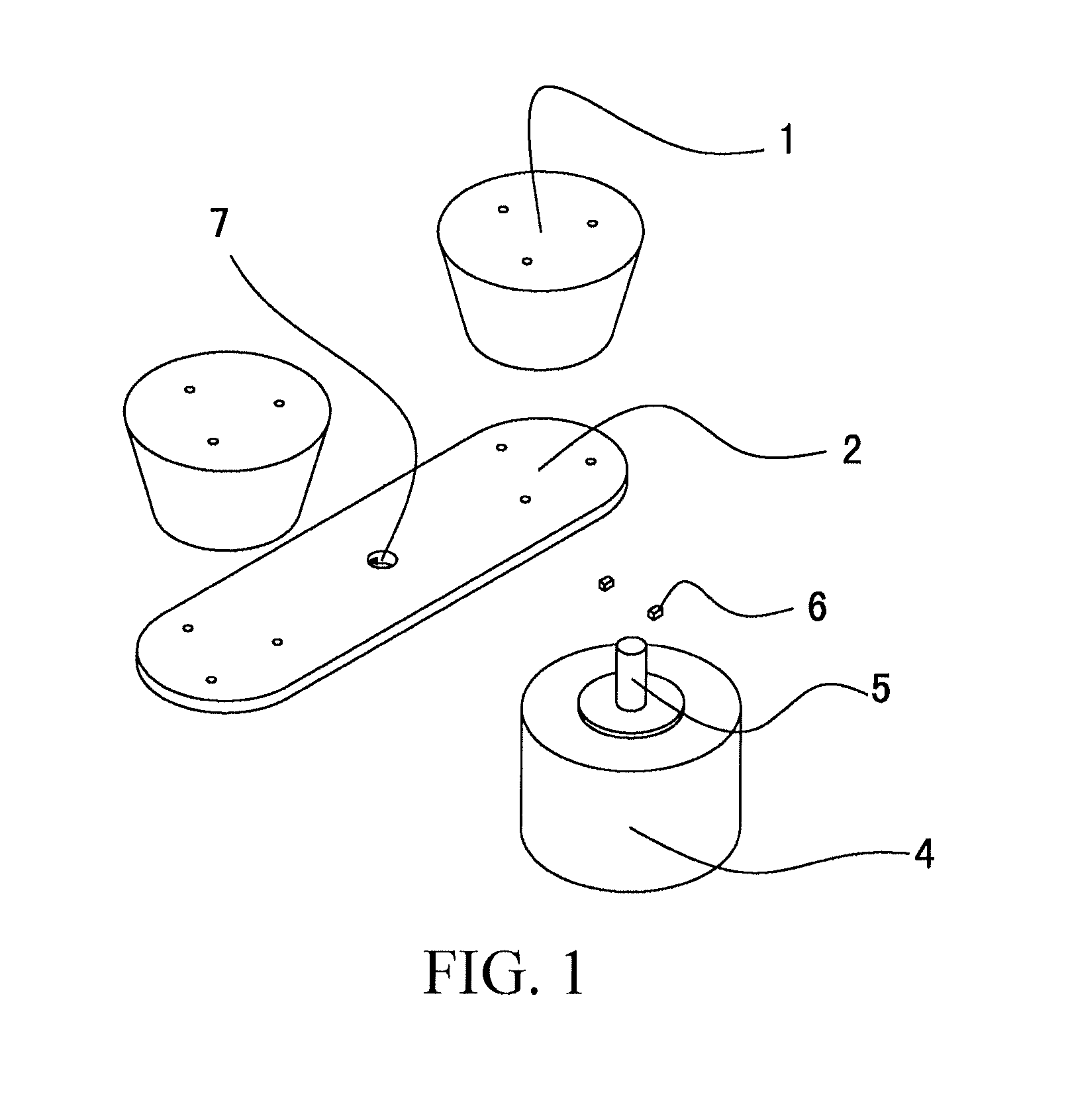
[0027] Referring to FIG. 1 and FIG. 2, the present invention mainly includes high field magnets 1, a magnetically permeable rotating arm 2 and a rotating electrical motor 4. In this embodiment, the magnetically permeable rotating arm 2 is made of an A3 steel plate, and during specific implementation, other magnetically permeable materials may also be adopted. The magnetically permeable rotating arm 2 is elongated, having two ends respectively fixedly mounted with one high field magnet 1. In this embodiment, the high field magnet 1 is in a shape of a cone. In this embodiment, a smaller surface (that is, a lower surface) of the high field magnet 1 is fixedly mounted on the magnetically permeable rotating arm 2, and is defined as a connecting surface of the magnet 1. A larger surface (that is, an upper surface) of the high field magnet 1 is a high magnetic field action surface, and is defined as a free surface of the magnet 1. In this embodiment, the high field magnet 1 is fixedly moun...

embodiment 2

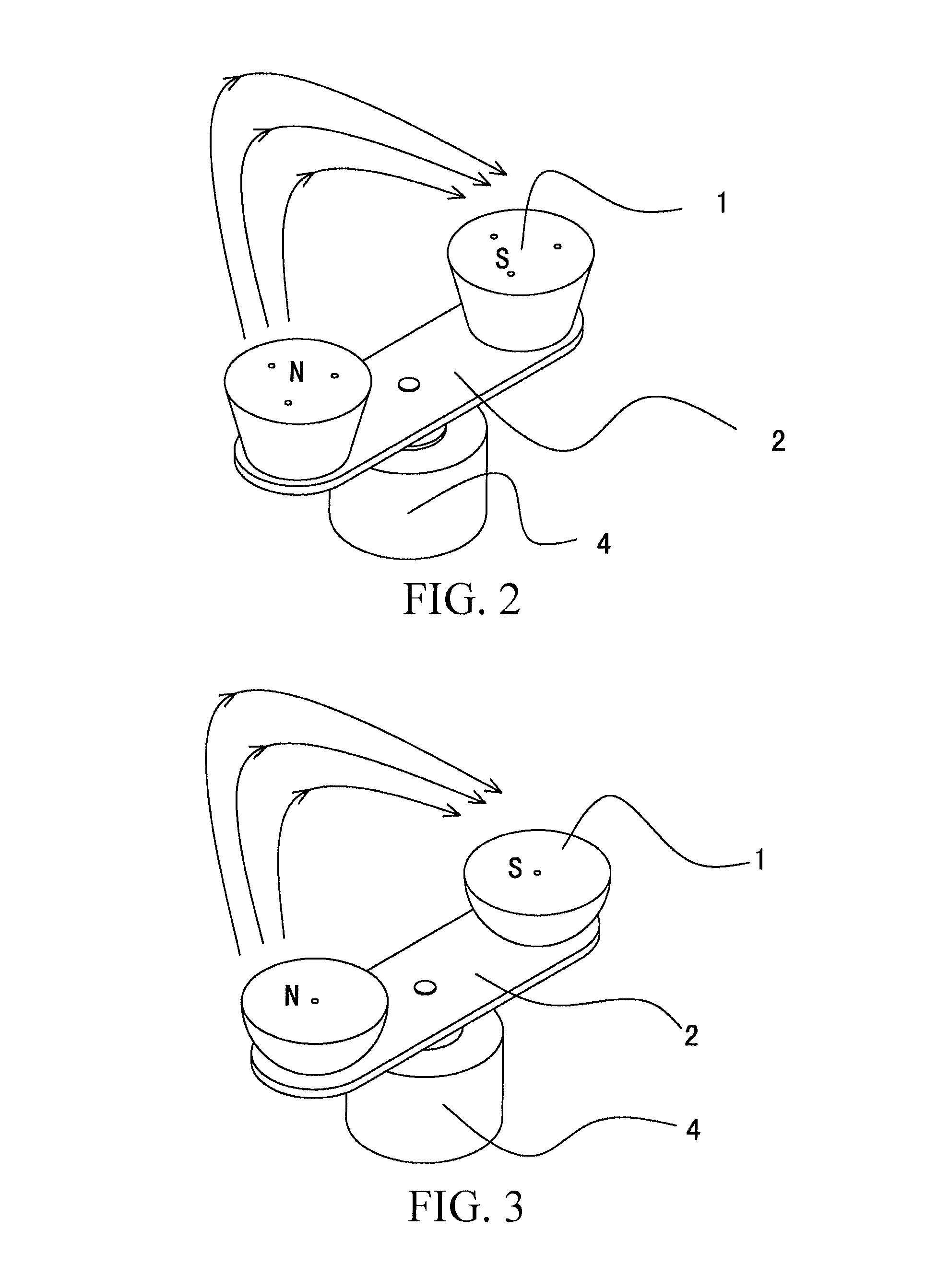
[0028] Referring to FIG. 3, this embodiment also includes high field magnets 1, a magnetically permeable rotating arm 2 and an electrical motor 4. In this embodiment, the high field magnet 1 is in a shape of a hemisphere. A lower surface (that is, a point on a spherical crown corresponding to a center of circle of a bottom surface) of the high field magnet 1 is fixedly mounted on the magnetically permeable rotating arm 2, and an upper surface (that is, a bottom plane) of the high field magnet 1 is a high magnetic field action surface. In this embodiment, the high field magnet 1 is fixedly mounted on the magnetically permeable rotating arm 2 through a screw, and during specific implementation, other connection manners may also be adopted. In this embodiment, the electrical motor 4 is also used to drive the magnetically permeable rotating arm 2 and the high field magnets 1 on the magnetically permeable rotating arm 2 to rotate at a low frequency.

embodiment 3

[0029] Referring to FIG. 4, this embodiment also includes high field magnets 1, a magnetically permeable rotating arm 2 and an electrical motor 4. In this embodiment, the high field magnet 1 is in a shape of a cone. A cross section of the high field magnet 1 is in a shape of an ellipse. A lower surface (that is, a smaller surface) of the high field magnet 1 is fixedly mounted on the magnetically permeable rotating arm 2, and an upper surface (that is, a larger surface) of the high field magnet 1 is a high magnetic field action surface. In this embodiment, the high field magnet 1 is fixedly mounted on the magnetically permeable rotating arm 2 through a screw, and during specific implementation, other connection manners may also be adopted. In this embodiment, the rotating electrical motor 4 is also used to drive the magnetically permeable rotating arm 2 and the high field magnets 1 on the magnetically permeable rotating arm 2 to rotate at a low frequency.


PUM

PropertyMeasurementUnit
frequency rotating constantaaaaaaaaaa
magnetic fieldaaaaaaaaaa
magnetic poleaaaaaaaaaa

Abstract

A method for implementing a low-frequency rotating constant high magnetic field is disclosed. The method includes disposing an even number of more than two high field magnets, and disposing a magnetically permeable rotating arm. The high field magnets are symmetrically and fixedly mounted on the same surface of the magnetically permeable rotating arm. Magnetic poles of free surfaces of two symmetrical high field magnets are opposite. The area of the free surface of the high field magnet is larger than that of a connecting surface. A cross section of the high field magnet is in a geometric shape without edges or corners. A rotating apparatus drives the magnetically permeable rotating arm and the high field magnets to rotate.

Description

BACKGROUND[0001]1. Technical Field[0002]The present invention relates to a method for implementing magnetic therapy, and more particularly to a method for implementing a low-frequency rotating constant high magnetic field.[0003]2. Related Art[0004]The magnetic field has an obvious influence on human body and other creatures, as well as water or chemical agents. In view of this, the magnetic field is applied to human body for local high magnetic field therapy, which is referred to as magnetic therapy. The magnetic therapy is not new in modern medicine, and magnetic therapy instruments are common, for example, Chinese Patent (Application No. 88214746.4) entitled “Electric Magnetic Therapy Apparatus”, Chinese Patent (Application No. 86206534) entitled “Magnetic Rotator for Medical Treatment”, and U.S. patent (U.S. Pat. No. 4,537,141) entitled “Magnetic Apparatus for Non-surgically Eliminating Calcium Deposit in Human Body”. However, all of the above patents have defects, and in view of...

Claims


Application Information

Patent Timeline
Patent Type & Authority Patents(United States)
IPC IPC(8): A61N2/00A61N2/08A61N2/06A61N2/12H01F7/02
CPCA61N2/12H01F7/0294
Inventor ZHANG, GONGBI
Owner SHENZHEN HENG AN HONG YUAN MAG TECH
Why Eureka
Try Eureka