Receiver circuit and associated method

a receiver circuit and receiver technology, applied in the direction of transmission, electrical equipment, etc., can solve the problems of large layout area, large layout area, increased power consumption and output noise, etc., and achieve the effect of reducing the amplitude of output signal

Active Publication Date: 2014-09-09
MEDIATEK INC
View PDF7 Cites 1 Cited by
  • Summary
  • Abstract
  • Description
  • Claims
  • Application Information

AI Technical Summary

Benefits of technology

[0014]An objective of the invention is providing a method applied to a receiver circuit. The receiver circuit includes two mixing paths and a filter; the two mixing paths are arranged to translate frequency band of an input signal, to scale the input signal by two mixing gains, to shift phase of the input signal by two mixing phase offsets, and to accordingly provide two mixed signal in response. The receiver circuit is arranged to provide an output signal in response to the two mixed signals. The method includes: receiving a test signal as the input signal, adjusting a mismatch setting which controls an amplitude difference between amplitudes of the two mixed signals and a phase difference between phases of the two mixed signals, observing amplitude of the output signal while adjusting the mismatch setting, and memorizing an optimal mismatch setting which minimizes amplitude of the output signal.

Problems solved by technology

However, the RC phase shifter increases power consumption and output noise, also occupies large layout area.
However, two ADCs consume extra power and layout areas.
High-order filter demands high power and large layout area.

Method used


Image

  • Receiver circuit and associated method
  • Receiver circuit and associated method
  • Receiver circuit and associated method

Examples


Embodiment Construction

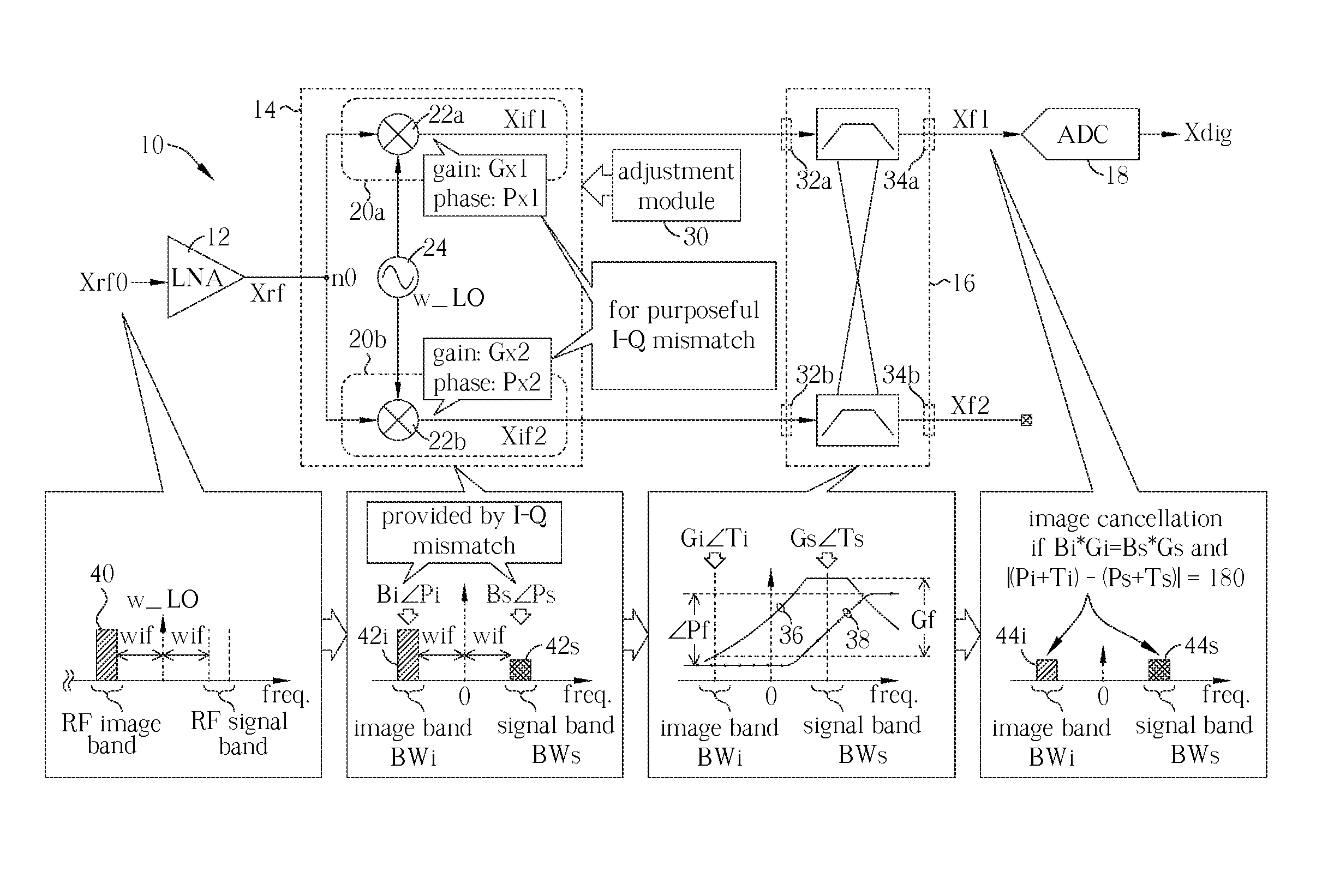
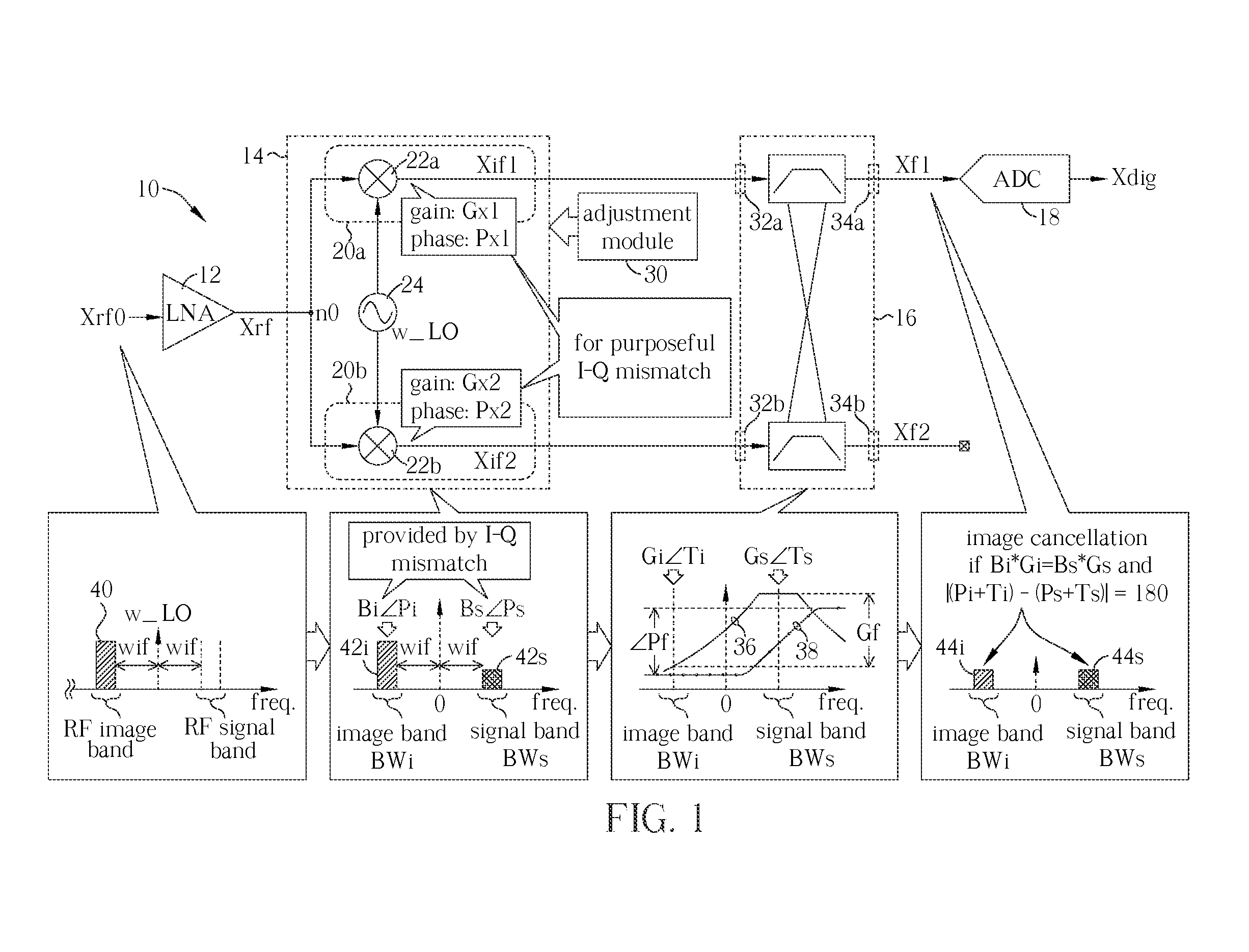
[0020]Please refer to FIG. 1 illustrating a receiver circuit 10 according to an embodiment of the invention; for example, the receiver circuit 10 can be a wireless RF receiver adopts low-IF receiving scheme. The receiver circuit 10 includes an amplifier 12 (e.g., a low-noise amplifier, LNA), a mixing block 14, an adjustment module 30, a filter 16 and an ADC 18. A signal Xrf0 received by the receiver circuit 10 is inputted to the amplifier 12 and amplified to a signal Xrf at a node n0. The mixing block 14 includes two mixing paths 20a and 20b; correspondingly, the filter 16, e.g., a complex band-pass filter, has two input terminals 32a and 32b, and two output terminals 34a and 34b. The mixing path 20a is coupled between the node n0 and the input terminal 32a, and the mixing path 20b is coupled between the node n0 and the input terminal 32b. The ADC 18 is coupled to the output terminal 34a.

[0021]In the mixing block 14, the mixing path 20a is arranged to translate frequency band of th...


PUM


Abstract

A receiver circuit, e.g., a low-IF receiver, including two mixing paths. The two mixing paths scale an input signal respectively by two mixing gains and shift phase of the input signal respectively by two mixing phase offsets to provide two mixed signals. The two mixing gains and the two mixing phase offsets are arranged to produce an amplitude adjustment between amplitudes of the two mixed signals and a phase difference of 90 degrees plus a phase adjustment between phases of the two mixed signals. With the amplitude adjustment and / or the phase adjustment properly tuned to nonzero value(s) in association with band-pass response of the receiver circuit, image rejection can be achieved and optimized. Associated method is also disclosed.

Description

[0001]This application claims the benefit of U.S. provisional application Ser. No. 61 / 702,340, filed Sep. 18, 2012, the subject matter of which is incorporated herein by reference.FIELD OF THE INVENTION[0002]The present invention relates to a receiver circuit and associated method, and more particularly, to a receiver circuit and associated method of low hardware complexity, power consumption and layout area.BACKGROUND OF THE INVENTION[0003]Wired and wireless networks, such as mobile telecommunication networks, local area networks, positioning systems, broadcasting systems, sensor networks etc., have become essential for modern daily life. In a network, when a transmitter needs to send digital information to a receiver, the transmitter encodes the digital information to a digital base-band (BB) signal, converts the digital base-band signal to an analog BB signal, modulates (up-converts) the analog BB signal to a radio-frequency (RF) signal by mixing the analog base-band signal with ...

Claims


Application Information

Patent Timeline
Patent Type & Authority Patents(United States)
IPC IPC(8): H04B1/10H04B1/26H04B1/16H04B1/30
CPCH04B1/16H04B1/30H04B2001/305
Inventor LIN, ANG-SHENGCHIU, WEI-HAO
Owner MEDIATEK INC
Why Eureka
Try Eureka