
Small-scale compound bow

a compound bow and small-scale technology, applied in the field of compound bows, can solve the problems of compact size, easy damage, and compact size of the current compound bow, and achieve the effects of less damage, less vibration, and increased speed of the arrow

Inactive Publication Date: 2014-09-16
PARK KYUNG SIN
View PDF12 Cites 41 Cited by
  • Summary
  • Abstract
  • Description
  • Claims
  • Application Information

AI Technical Summary

Benefits of technology

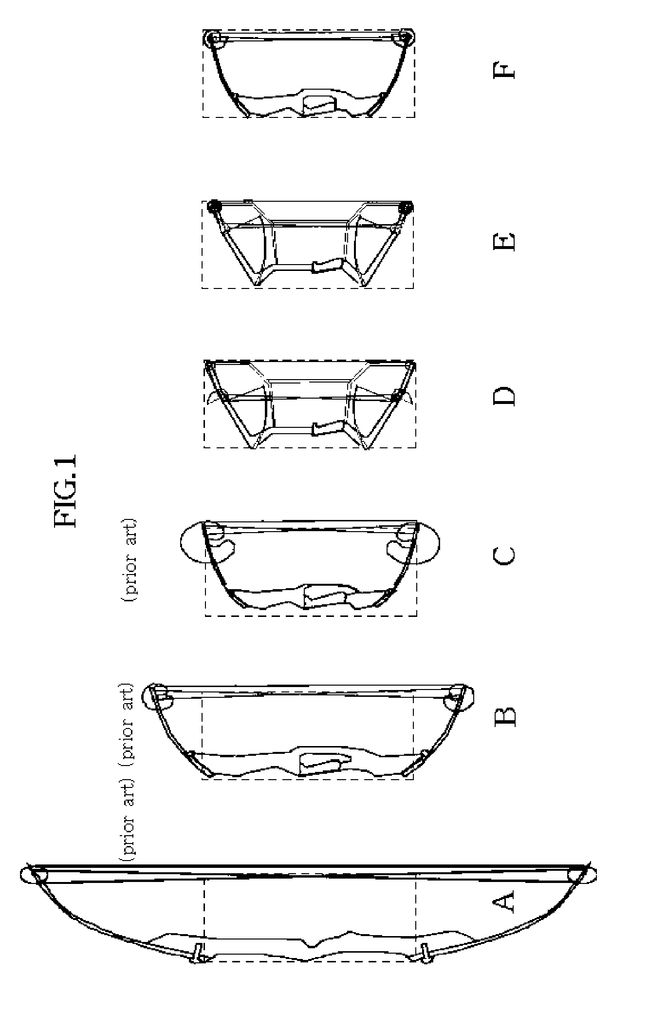
The present invention provides a differential motion cam for a compound bow that is smaller and thicker than the cam used in the recent compound bow with a short distance between axles. This allows for a smaller bow and less damage to the cam. Additionally, the bow has a smooth motion of a limb, increases the speed of an arrow, and reduces vibrations when shooting arrows. The bow is also easier to port and shoot in bush or with obstacles.

Problems solved by technology

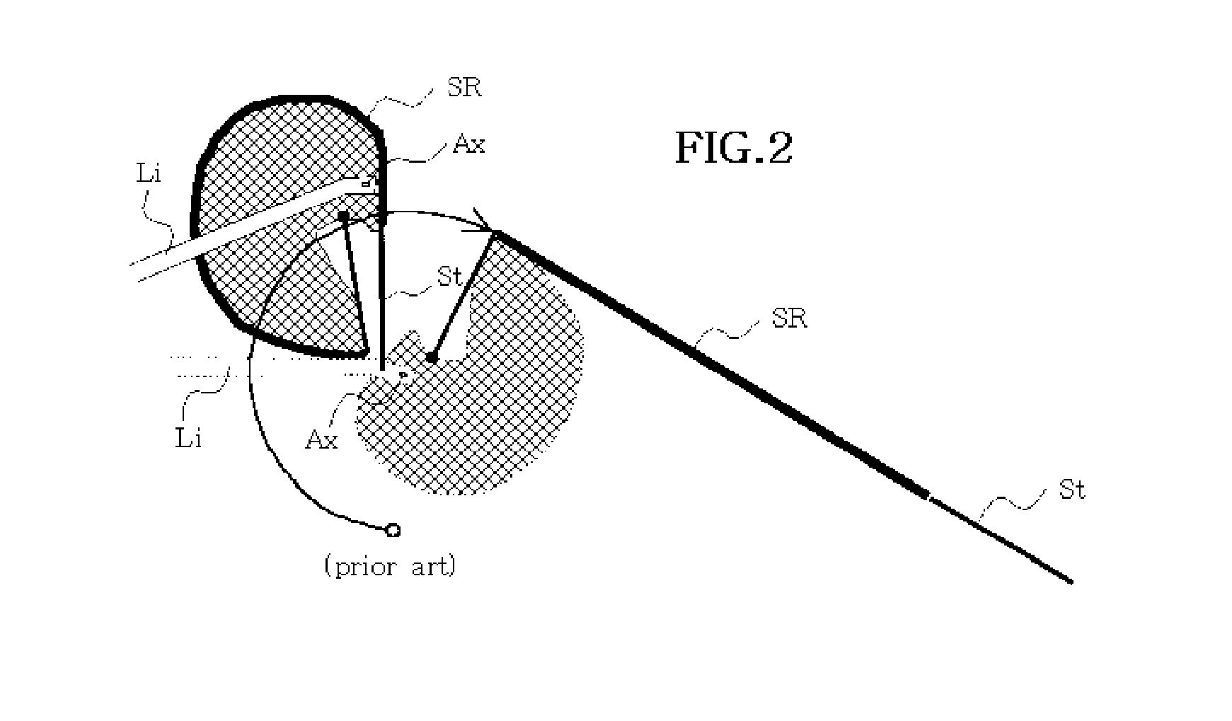
Since a large cam made of a light metal is positioned at an end portion of a limb, it might be easily damaged.
The currently used compound bow has become compact-sized as compared with an original compound bow; however it is heavy, and a cam is thin and large, so it can be easily damaged.

Method used


Image

  • Small-scale compound bow
  • Small-scale compound bow
  • Small-scale compound bow

Examples


Embodiment Construction

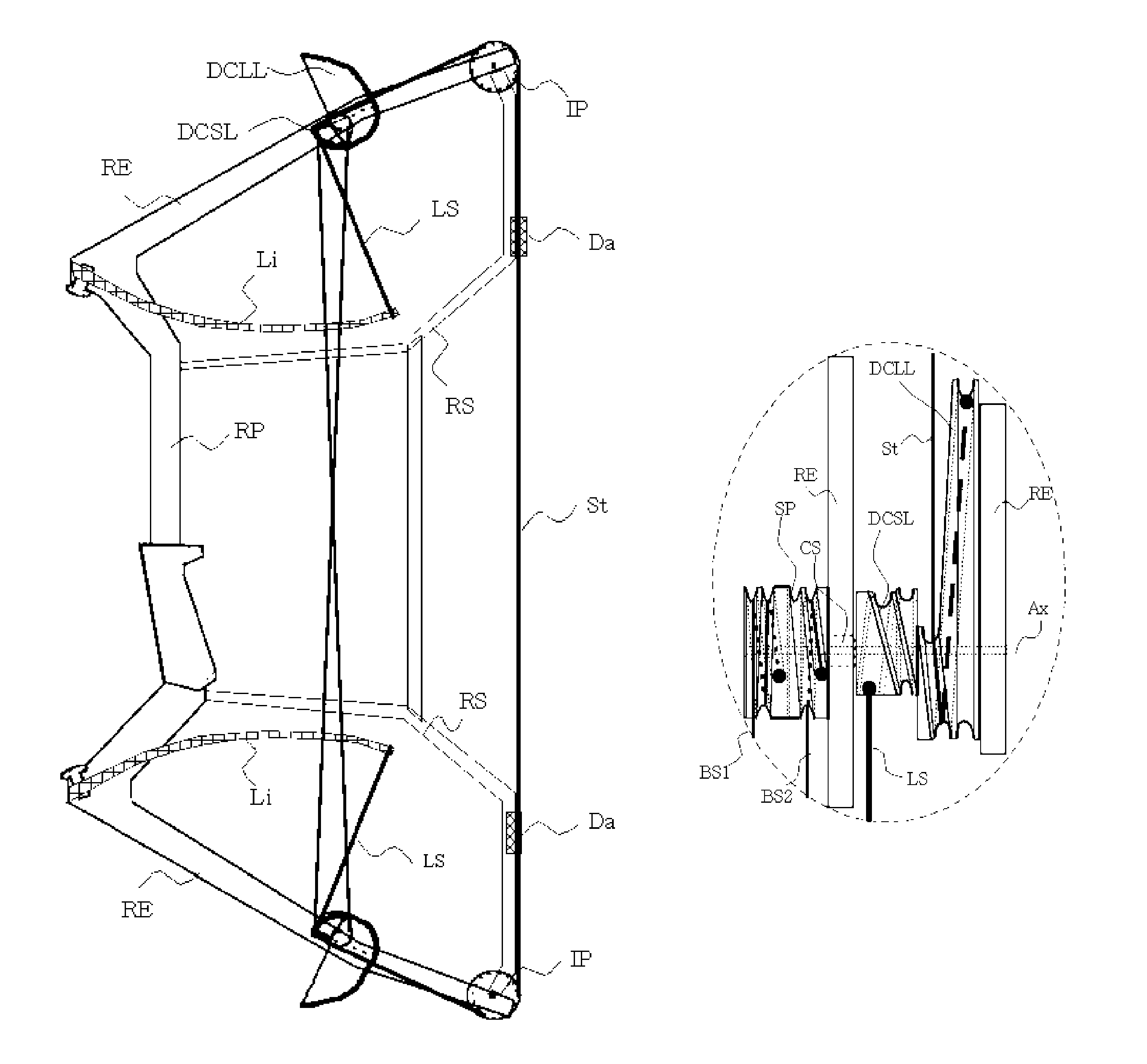
[0078]First of all, the compound bow which adapts a differential motion cam with a lot of rotational amount as shown in FIG. 3 and an idler pulley (IP) will be described, and in the modes for carrying out the invention the compound bow of another embodiment and other elements will be described.

[0079]The idler pulley (IP) provided at an end portion of the riser extended (RE) is manufactured in the manner as shown in FIG. 6. The groove is formed deep enough to prevent the string (St) from derailing, and it is formed not to be too large while caring not to damage it but the radius of it is not limited.

[0080]The differential cam large lobe (DOLL) rotating about 360°, the differential cam small lobe (DCSL), the connecting shaft (CS) and the synchronizing pulley (SP) are manufactured in the manner as shown in FIG. 7. As not shown in the drawings, part of the riser extended (RE) is manufactured in a detachable type, so it can be easily assembled to the riser extended (RE).

[0081]The size of...


PUM


Abstract

The present invention relates to archery, and more specifically relates to a compound bow of reduced size and weight comprising short limbs (Li), small pulleys and small cams while maintaining the performance of the prior art by linking a differential motion cam and a differential motion pulley of a novel design. The present invention has devised a method for dispensing with large cams and decreasing the scale of compound bows by using three different stratagems. The compound bow is decreased in scale through 1. the use of an idler pulley (IP) and a differential motion cam which rotates by a large extent as shown in FIG. 3, 2. the use of both a Y-cam (YC) which rotates by a large extent and a differential motion cam as shown in FIG. 11, and 3. the use of a combination of Y-cams (YC) which rotate by a large extent as shown in FIG. 16; and this compound bow can be used, by way of example, for hunting and sports and for shooting ropes for life saving purposes.

Description

RELATED APPLICATIONS[0001]This application is a 371 application of International Application No. PCT / KR2011 / 000882, filed Feb. 10, 2011, which in turn claims priority from Korean Patent Application Nos. 10-2010-0103749, filed Oct. 23, 2010, 10-2010-0035300, filed Apr. 16, 2010, 10-2010-0023200, filed Mar. 16, 2010, 10-2010-0015607, filed Feb. 22, 2010, and 10-2010-0014042, filed Feb. 17, 2010, each of which is incorporated herein by reference in its entirety.TECHNICAL FIELD[0002]The present invention relates to archery, and in particular to a small scale compound bow which is equipped with a differential motion pulley and a differential motion cam.BACKGROUND ART[0003]A compound bow has been being improved for almost 40 years since its invention in 1969 as the size of it has become compact-sized whereas forgiveness is being enhanced, and the speed of an arrow becomes faster.[0004]The above-mentioned improvements thank to the use of new materials and new designs of cam.[0005]The cams ...

Claims


Application Information

Patent Timeline
Patent Type & Authority Patents(United States)
IPC IPC(8): F41B5/10F41B5/00
CPCF41B5/105F41B5/0094F41B5/10
Inventor PARK, KYUNG, SIN
Owner PARK KYUNG SIN
Learn More