Methods and apparatus for a manual vascular compression device

a compression device and vascular technology, applied in the field of manual vascular compression devices, can solve the problems of fatigue, hypovolemia, shock, and possibly death of patients, and achieve the effect of facilitating hemostasis

Active Publication Date: 2014-09-16
MARINE POLYMER TECH
View PDF25 Cites 3 Cited by
  • Summary
  • Abstract
  • Description
  • Claims
  • Application Information

AI Technical Summary

Benefits of technology

[0015]An object of the invention is to assist a user in controlling bleeding and achieving hemostasis with a hand held device that allows for compression of a puncture site at both the skin level and blood vessel level simultaneously.
[0022]In another preferred embodiment, the vascular compression apparatus is formed as a unitary member with the pad permanently connected to the elongate shaft, thereby requiring no assembly or disassembly by the user and which further allows for easy and complete sterilization. In a most preferred embodiment the unitary vascular compression apparatus is disposable.

Problems solved by technology

If, for example, a sheath is removed from the femoral artery in the groin and no attempt to stem the bleeding is made, the patient would quickly experience severe bleeding which would resort in significant consequences including hypovolemia, shock, and possibly death.
This can result in fatigue, stiffness and / or pain in the fingers, hands, wrist and forearms of the individual performing the procedure.
Prolonged or repeated performance of this procedure may result in a repetitive stress injury such as carpal tunnel syndrome.
The direct pressure method also puts the individual administering pressure at risk for direct exposure to the patient's blood.
These automated compression devices are far from ideal, however.
They tend to be expensive, difficult to maintain in good working order, consume a great deal of space and are difficult to keep sterile.
This type of device has a number of disadvantages including: the cost of the apparatus; the difficulty associated in ensuring a minimal level of cleanliness; and the time associated in connecting the disposable disk to the assembly prior to its use on a patient.

Method used


Image

  • Methods and apparatus for a manual vascular compression device
  • Methods and apparatus for a manual vascular compression device
  • Methods and apparatus for a manual vascular compression device

Examples


Embodiment Construction

[0033]To more clearly set forth the invention, reference will be made to the embodiments illustrated in the drawings and specific language will be used. Nevertheless, it should be understood that the invention should not be deemed limited to particular embodiments, descriptions or drawings contained herein.

[0034]The vascular compression apparatus of the invention is used on a patient to apply pressure on an area near or at a wound site, such as a blood vessel puncture, most often after a cannulated procedure such as angioplasty, for the purpose of controlling the patient's bleeding and, further, of achieving hemostasis.

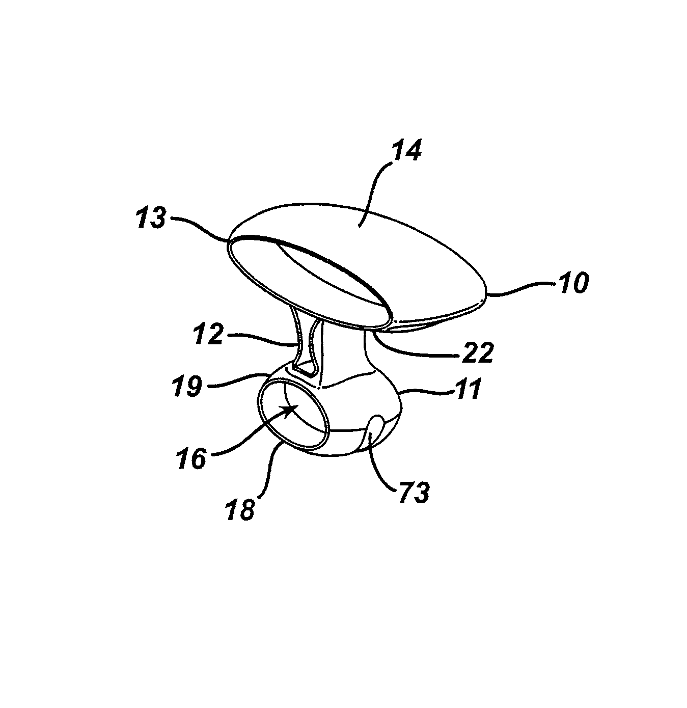
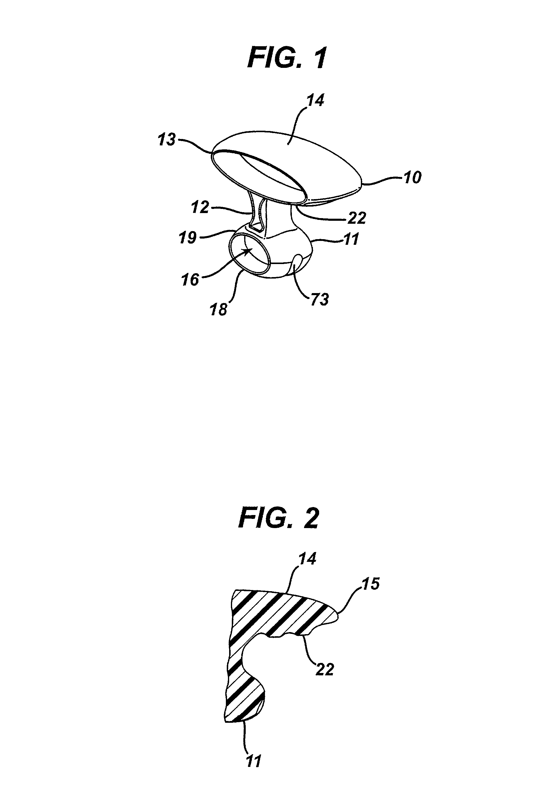
[0035]FIG. 1 shows the manual vascular compression device of the invention 10. The device has a handle 13 having a top 14 and a bottom 22, a shaft 12 and a pad 11. The handle 13 is connected, generally off-center, to the proximal end of the shaft 12. The pad 11 is connected to the distal end of the shaft 12 and is generally centered on the top surface 19 of the pad 11...


PUM


Abstract

A vascular compression apparatus and method for applying pressure onto an area of a patient generally including a blood vessel and a wound site, such as a blood vessel puncture, after a cannulated procedure for the purpose of controlling bleeding and achieving hemostasis. The vascular compression apparatus includes a handle, a shaft and a pad. The shaft extends generally downward from the center of the bottom side of the handle. The pad is connected generally off-center of its top side to the bottom end of the shaft. The bottom side of the pad is convex to allow the vascular compression device to be rocked back and forth. In use, the pad is generally placed proximal to the catheter insertion site and over the blood vessel containing the catheter. The device is rocked proximally to control blood flow while removing the catheter. After the catheter is removed from the puncture site, the device is rocked distally to the puncture site, where pressure is applied until hemostasis is achieved.

Description

CROSS REFERENCE TO RELATED APPLICATIONS[0001]The present application claims the benefit of a U.S. application entitled “Methods and Apparatus for a Manual Vascular Compression Device,” bearing Ser. No. 11 / 092,369, filed Mar. 29, 2005, the entire contents of which are hereby incorporated herein by reference.FIELD OF THE INVENTION[0002]This invention relates in general to a manual vascular compression device and in particular to a manual femoral compression device.BACKGROUND OF THE INVENTION[0003]This invention relates to a vascular compression apparatus and method for controlling bleeding and achieving hemostasis by applying pressure onto an area of a patient including a wound site, such as a blood vessel puncture, and a blood vessel. In particular, this invention relates to a vascular compression device and a method for controlling bleeding and facilitating hemostasis following percutaneous catheterization via the femoral artery or vein.[0004]The femoral artery is a high pressure bl...

Claims


Application Information

Patent Timeline
Patent Type & Authority Patents(United States)
IPC IPC(8): A61B17/00A61B17/12
CPCA61B17/12A61B2017/12004
Inventor FINKIELSZTEIN, SERGIOFINKIELSZTEIN, MARCOVOURNAKIS, JOHN N.
Owner MARINE POLYMER TECH
Why Eureka
Try Eureka