Tissue fusion system and method of performing a functional verification test

a functional verification and tissue fusion technology, applied in the field of new and improved functional verification tests, can solve the problems of limiting or inhibiting the ability to perform reliable thermal tissue operations as intended, reducing the chance that a problem related to the heating elements of the jaw will go unnoticed, etc., to prolong the initial surgical procedure and reduce the trauma on the patient

Inactive Publication Date: 2014-09-23
CONMED CORP
View PDF89 Cites 805 Cited by
  • Summary
  • Abstract
  • Description
  • Claims
  • Application Information

AI Technical Summary

Benefits of technology

[0011]It is desirable to identify potential problems with a thermal tissue operating system that might develop as a result of ongoing use of the system during a surgical procedure. An early identification of any problem avoids subsequent surgical complications and reduces the trauma on the patient caused by prolonging the initial surgical procedure or by performing subsequent surgical procedure to correct an inadequate thermal tissue operation performed during the prior surgical procedure.
[0012]The present invention relates to a functional verification test which is performed on an ongoing basis, between thermal tissue operations conducted during the course of the entire surgical procedure, to detect potential problems in the performance of the thermal tissue operating system which might arise due to ongoing use during the course of its use in the procedure. Specifically, an ongoing functional verification test described herein recognizes the possibility of changes occurring in the jaw heating elements during the course of the procedure and that those changes may limit or inhibit the ability to perform reliable thermal tissue operations as intended. The functional verification test reduces the chances that a problem related to the jaw heating elements will go unnoticed during some part of the surgical procedure.

Problems solved by technology

Specifically, an ongoing functional verification test described herein recognizes the possibility of changes occurring in the jaw heating elements during the course of the procedure and that those changes may limit or inhibit the ability to perform reliable thermal tissue operations as intended.
The functional verification test reduces the chances that a problem related to the jaw heating elements will go unnoticed during some part of the surgical procedure.

Method used


Image

  • Tissue fusion system and method of performing a functional verification test
  • Tissue fusion system and method of performing a functional verification test
  • Tissue fusion system and method of performing a functional verification test

Examples


Embodiment Construction

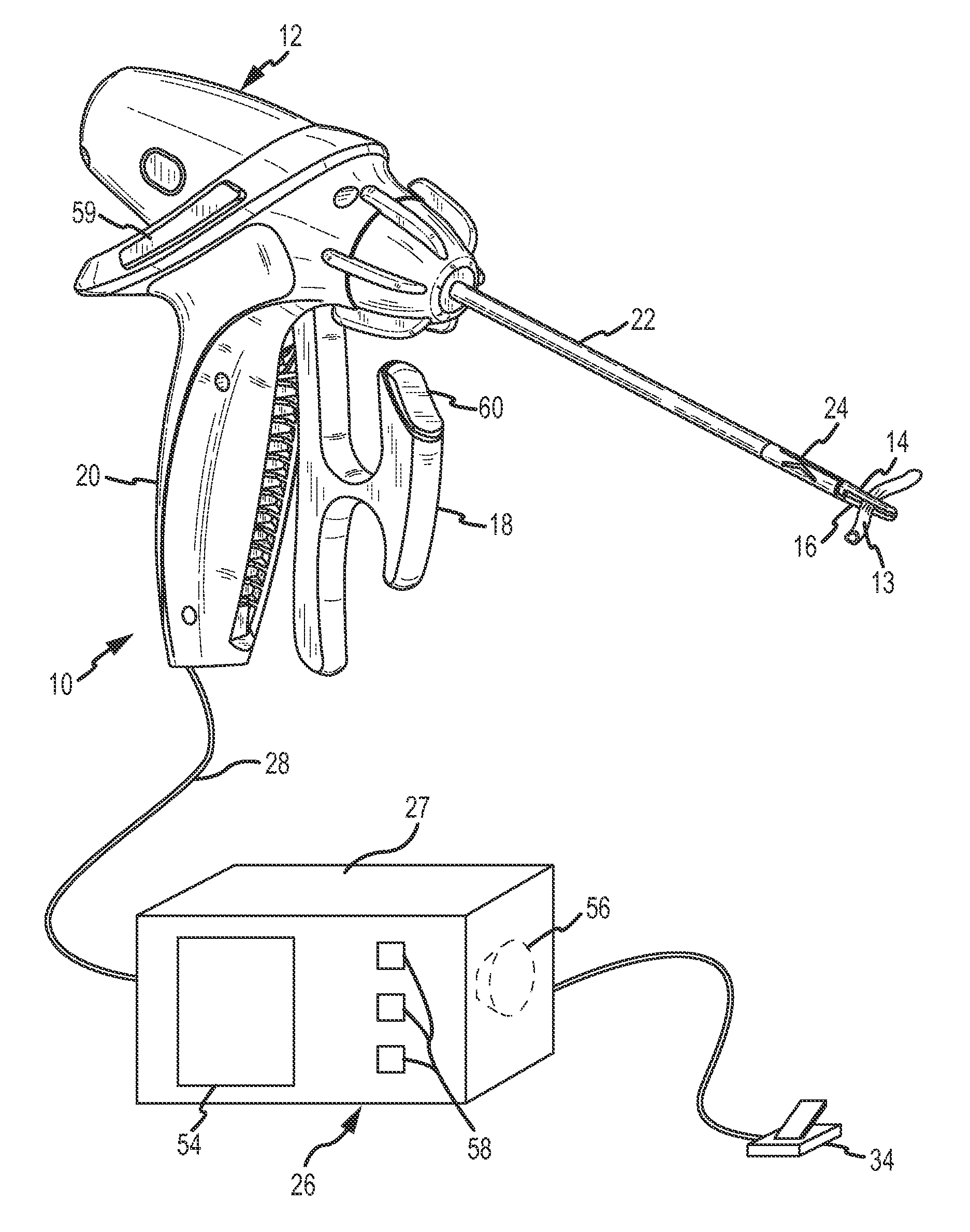
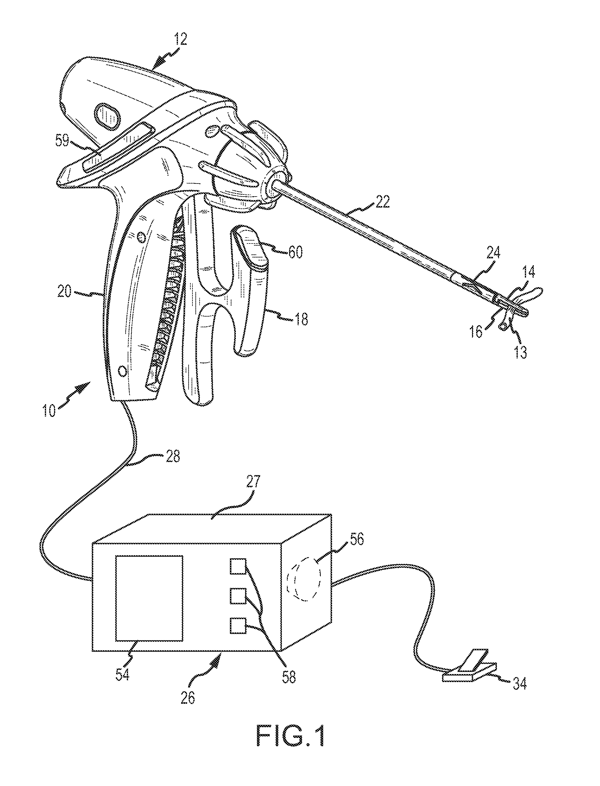
[0028]A thermal tissue operating system 10 in which the present invention is incorporated is shown in FIG. 1. The system 10 includes a handpiece 12 which is manipulated by a surgeon to grasp and compress tissue (exemplified by a vessel 13) between jaws 14 and 16 of the handpiece 12, and to simultaneously apply thermal heat energy from the jaws 14 and 16 to the compressed tissue in a thermal tissue operation. The thermal tissue operation may seal multiple pieces of the tissue together, cut a single piece of tissue into separate parts, or sequentially seal and then cut tissue.

[0029]The jaws 14 and 16 are brought together to compress the tissue by squeezing a lever 18 toward an adjacent handgrip 20 of the handpiece 12. Internal mechanical components of the handpiece 12 (not shown but described in the above-application Ser. No. 12 / 842,399 convert the pivoting movement of the lever 18 relative to the handgrip 20 into motion which is transferred through a shaft 22 to a jaw movement mechan...


PUM


Abstract

A jaw heating element of a handpiece of a thermal tissue operating system is tested on an ongoing basis by supplying a test heater power signal to the jaw heating element between individual thermal tissue operations. Voltage and current through the jaw heating element is sensed and the resistance of the jaw heating element is calculated. If the calculated resistance is outside a range of predetermined acceptable values, an error condition is indicated.

Description

CROSS REFERENCE TO RELATED INVENTIONS[0001]This invention is related to those inventions described in U.S. patent application Ser. No. 12 / 842,327 filed Jul. 23, 2010, titled Jaw Movement Mechanism and Method for Surgical Tool, and U.S. patent application Ser No. 12 / 842,399 filed Jul. 23, 2010, titled Surgical Tool and Method Using Crossbar Lever, and U.S. patent application Ser No. 12 / 842,606 filed Jul. 23, 2010, titled Tissue Fusion System and Method for Performing a Self Test, all of which are filed concurrently herewith and all of which are assigned to the assignee hereof. The subject matter of these applications is incorporated herein by this reference.FIELD OF THE INVENTION[0002]This invention relates to a thermal tissue operating system, which is also referred to generically as a tissue fusion system. More particularly, the present invention relates to a new and improved functional verification test in which jaw heating elements of a handpiece of the thermal tissue operating s...

Claims


Application Information

Patent Timeline
Patent Type & Authority Patents(United States)
IPC IPC(8): A61B18/08A61B17/00A61B18/00A61B18/10
CPCA61B18/085A61B2017/00725A61B2018/0063A61B2018/00666A61B2017/00973A61B18/10A61B2018/00714A61B2018/00791A61B2017/00199A61B2018/00892A61B2018/00827A61B2017/00123A61B2018/00875A61B2017/0003
Inventor STUEBE, BRIAN, C.
Owner CONMED CORP
Why Eureka
Try Eureka