
Circuit arrangement for generation of radio frequency output signals which form a broadband frequency ramp

a technology of radio frequency output and circuit arrangement, which is applied in the direction of pulse automatic control, radio transmission, electrical apparatus, etc., can solve the problems of large tuning bandwidth of vc oscillators, poor control, and large noise suppression of input-side phase noise, so as to reduce reduce the additional cost of voltage supply and cooling. , the effect of reducing the number of interfaces

Active Publication Date: 2014-09-23
KROHNE MESSTECHNICK GMBH & CO KG
View PDF8 Cites 2 Cited by
  • Summary
  • Abstract
  • Description
  • Claims
  • Application Information

AI Technical Summary

Benefits of technology

[0028]The high-level integration which has been described as preferable above, on the one hand, minimizes the costs by a reduced number of interfaces and, on the other hand, enables a power-saving implementation in which the additional costs for the voltage supply and cooling are low keep, and enables applications with strictly limited energy budget. In particular in industrial measurement engineering the available electrical output is severely limited when using a 2-wire unit signal.

Problems solved by technology

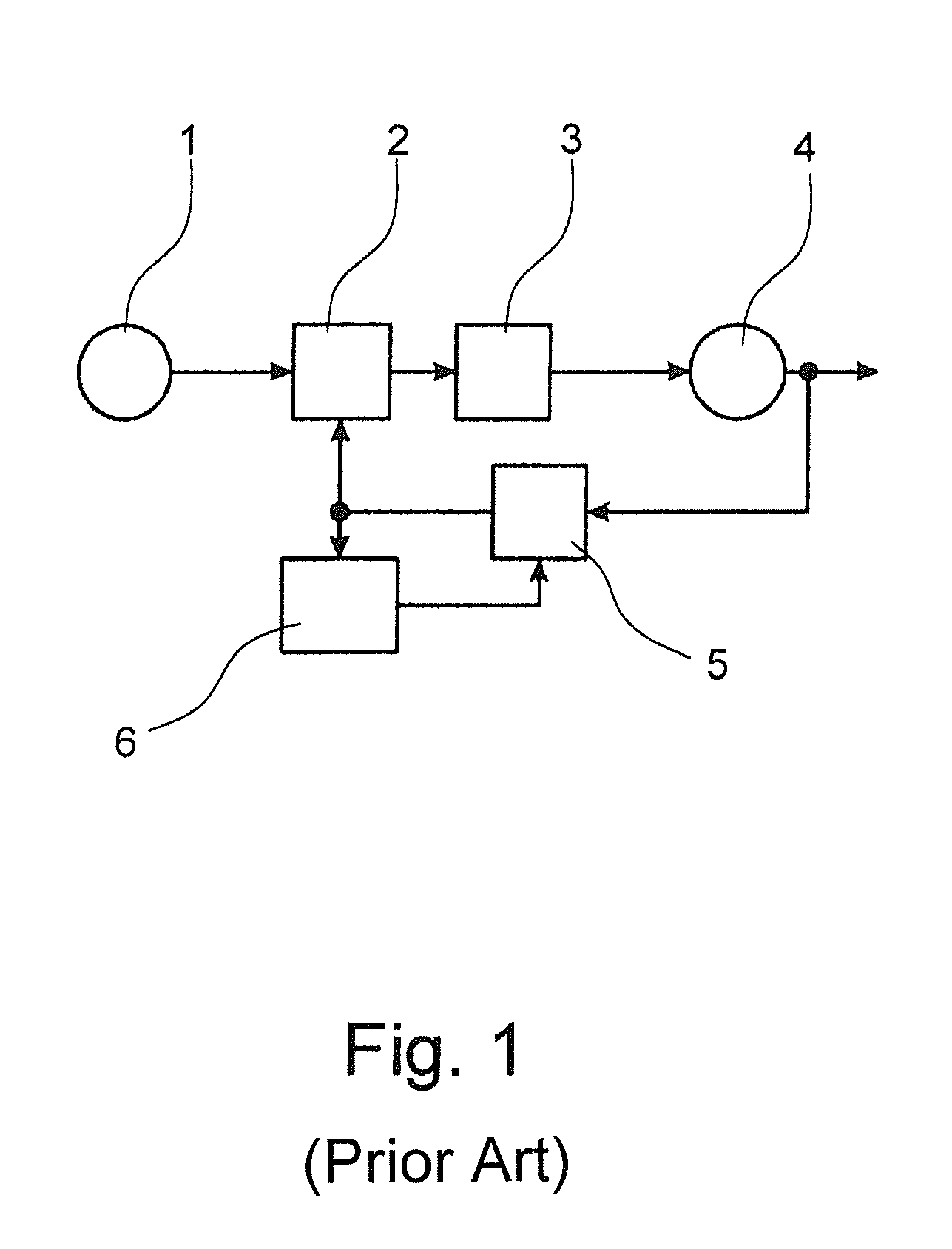
In this frequency range then in any case the loop filter 3 deviates from the integral behavior and, as a result of which control is poor, especially noise suppression of the input-side phase noise.
These two effects act unfavorably in the same direction and thus mutually reinforce each other.
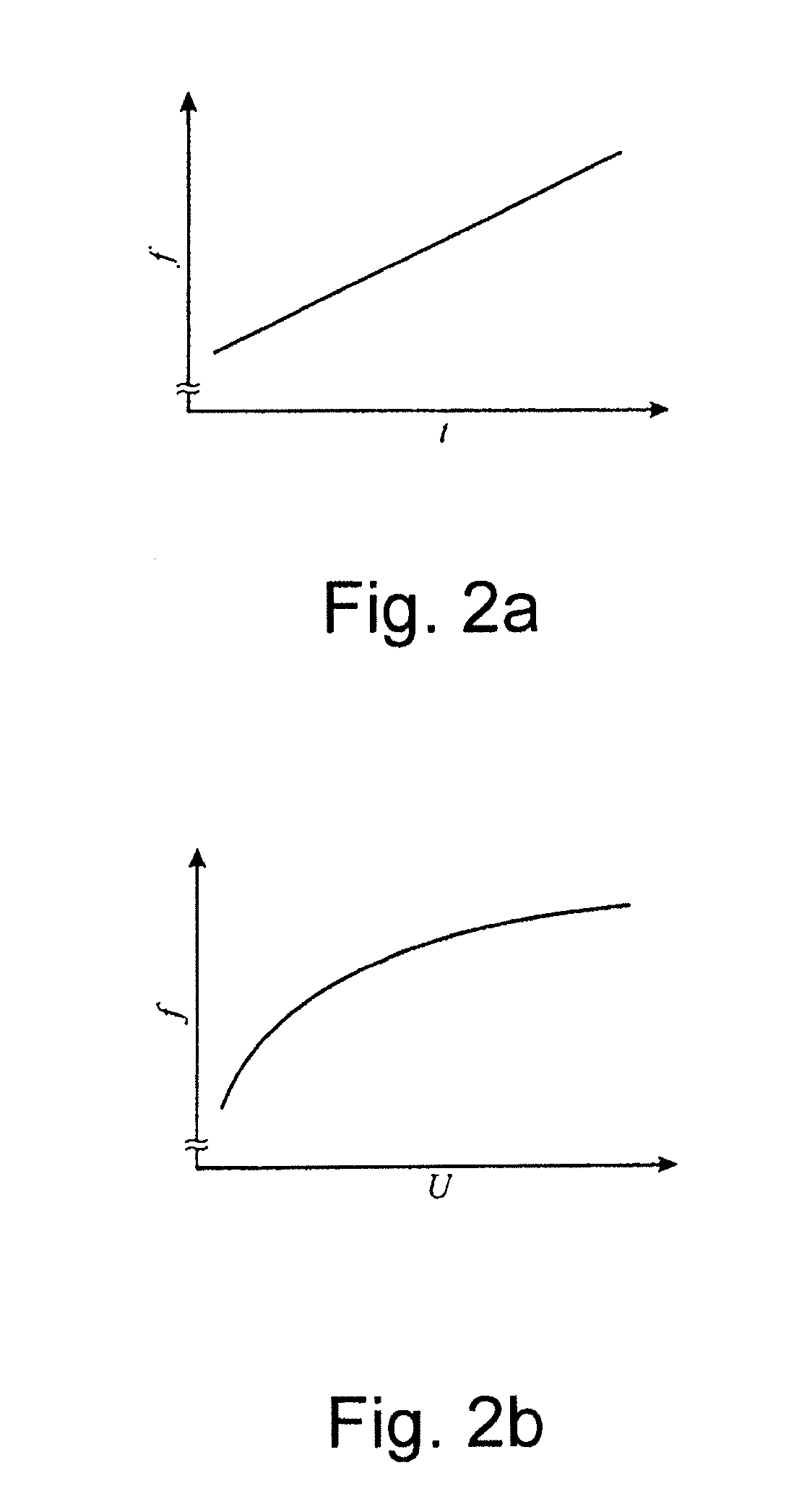
In any case, very broadband frequency ramps also require VC oscillators with a very large tuning bandwidth, which can only be accomplished by a large tuning steepness.
This large tuning steepness causes marginal interferences of the tuning voltage, and of the input voltage on the VC oscillator, like any digital or analog circuit inevitably causes, to induce modulation of the frequency of the radio frequency output signals so that in PLLs for broadband frequency ramps the path from the phase detector 2 to the VC oscillator 4 is very unfavorable for introducing additional circuits.

Method used


Image

  • Circuit arrangement for generation of radio frequency output signals which form a broadband frequency ramp
  • Circuit arrangement for generation of radio frequency output signals which form a broadband frequency ramp
  • Circuit arrangement for generation of radio frequency output signals which form a broadband frequency ramp

Examples


Embodiment Construction

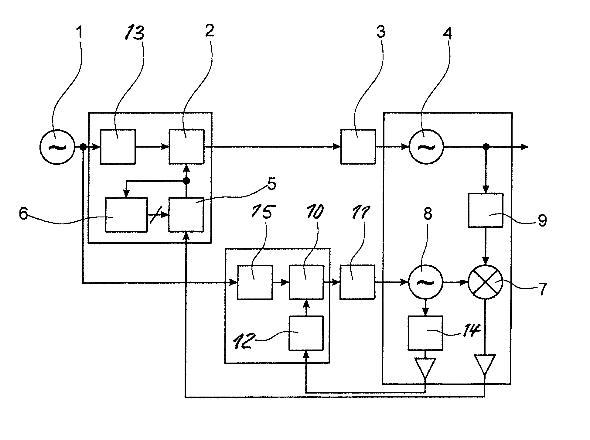
[0036]FIGS. 3 to 5 show preferred exemplary embodiments of circuit arrangements in accordance with the invention for generation of radio frequency output signals which form a broadband frequency ramp. These circuit arrangements include a reference oscillator 1, a phase detector 2, a loop filter 3, a voltage-controlled oscillator (i.e., a VC oscillator) 4 for generating the radio frequency output signals, a frequency divider 5 with an assigned control unit 6, with which the division factor N of the frequency divider 5 can be set, a step-down mixer 7 and a local oscillator 8 for generating a local oscillator signal. Here the phase-locking loop includes the reference oscillator 1, the phase detector 2, the loop filter 3, the VC oscillator 4, the frequency divider 5 and the step-down mixer 7. The frequency divider 5 and the step-down mixer 7 are in the feedback path of the phase-locking loop. The step-down mixer 7 mixes the output signal (of the VC oscillator 4) and the local oscillator...


PUM


Abstract

A circuit arrangement for generation of radio frequency output signals which form a broadband frequency ramp, with a reference oscillator, a phase detector, a loop filter, a VC oscillator for generating the output signals, a frequency divider, a step-down mixer and a local oscillator for generating a local oscillator signal. The reference oscillator, the phase detector, the loop filter, the VC oscillator, the frequency divider and the step-down mixer belong to a phase-locking loop. The frequency divider and the step-down mixer are in the feedback path of the phase-locking loop. The step-down mixer mixes the output signals and the local oscillator signal. The frequency of the output signal is adjustable by varying the division ratio of the frequency divider. Characteristics of the output signal are improved using the adjustable frequency of the local oscillator signal.

Description

FIELD OF THE INVENTION[0001]The invention relates to a circuit arrangement for generation of radio frequency output signals which form a broadband frequency ramp, with a reference oscillator, a phase detector, preferably a loop filter, a voltage-controlled oscillator (i.e., VC oscillator) for generating the output signals. A frequency divider, a step-down mixer and a local oscillator generate a local oscillator signal. The reference oscillator, the phase detector, optionally the loop filter, the VC oscillator, the frequency divider and the step-down mixer belong to a phase-locking loop. The frequency divider and the step-down mixer are in the feedback path of the phase-locking loop. The step-down mixer mixes the output signals and the local oscillator signal. The frequency of the output signal is adjustable by variation of the division ratio of the frequency divider.BACKGROUND OF THE INVENTION[0002]Circuit arrangements for generation of radio frequency output signals which form a br...

Claims


Application Information

Patent Timeline
Patent Type & Authority Patents(United States)
IPC IPC(8): H03L7/00H03L7/185H03L7/23
CPCH03L7/185H03L7/235H03L2207/12H03L2207/05
Inventor MUSCH, THOMASPOHL, NILS
Owner KROHNE MESSTECHNICK GMBH & CO KG
Learn More