Height control

a height control and height technology, applied in the field of height control, can solve the problems of inability to determine the reliable ground level, the lowering of the sprayer boom, and the collision between the boom and the approaching crop

Active Publication Date: 2014-09-23
NORAC SYST INT
View PDF6 Cites 24 Cited by
  • Summary
  • Abstract
  • Description
  • Claims
  • Application Information

AI Technical Summary

Problems solved by technology

If the sprayer boom is being controlled such that a fixed separation between the top of the crop and the sprayer boom is being maintained then this erroneous interpretation of the reflection from the soil as a top of crop signal will cause the sprayer boom to be lowered to maintain the predetermined separation.
However, the separation in this case would be between the sprayer boom and the ground level which has been erroneously interpreted as corresponding to the top of the crop.
This temporary absence of the crop in the transmission path of the ultrasonic sensor will result in the sprayer boom being lowered much further than would be the case if a true reflection had been received from the top of the crop.
In any case, it is likely the boom will have been lowered below the true level of the top of the crop and thus a collision between the boom and the approaching crop may occur.
If height control with respect to the local ground level is being carried out, such as in the example of a harvester cutter bar, then situations can arise in which a reliable ground level cannot be determined or where, due to either matter resting on the ground or vegetation and the like being present under the sensors, an erroneous ground level is determined.
In the first case, a ground level controlled system can become inoperable if it cannot determine a reliable ground level.

Method used


Image

  • Height control
  • Height control
  • Height control

Examples


Embodiment Construction

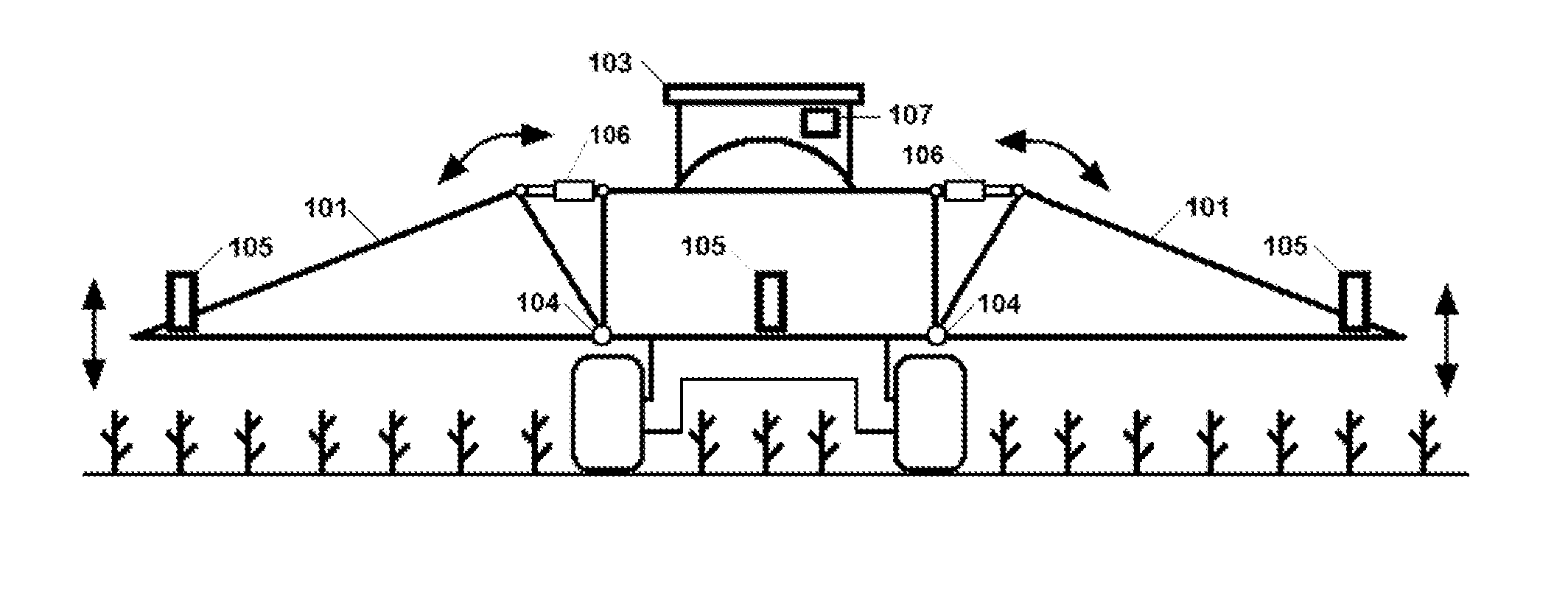
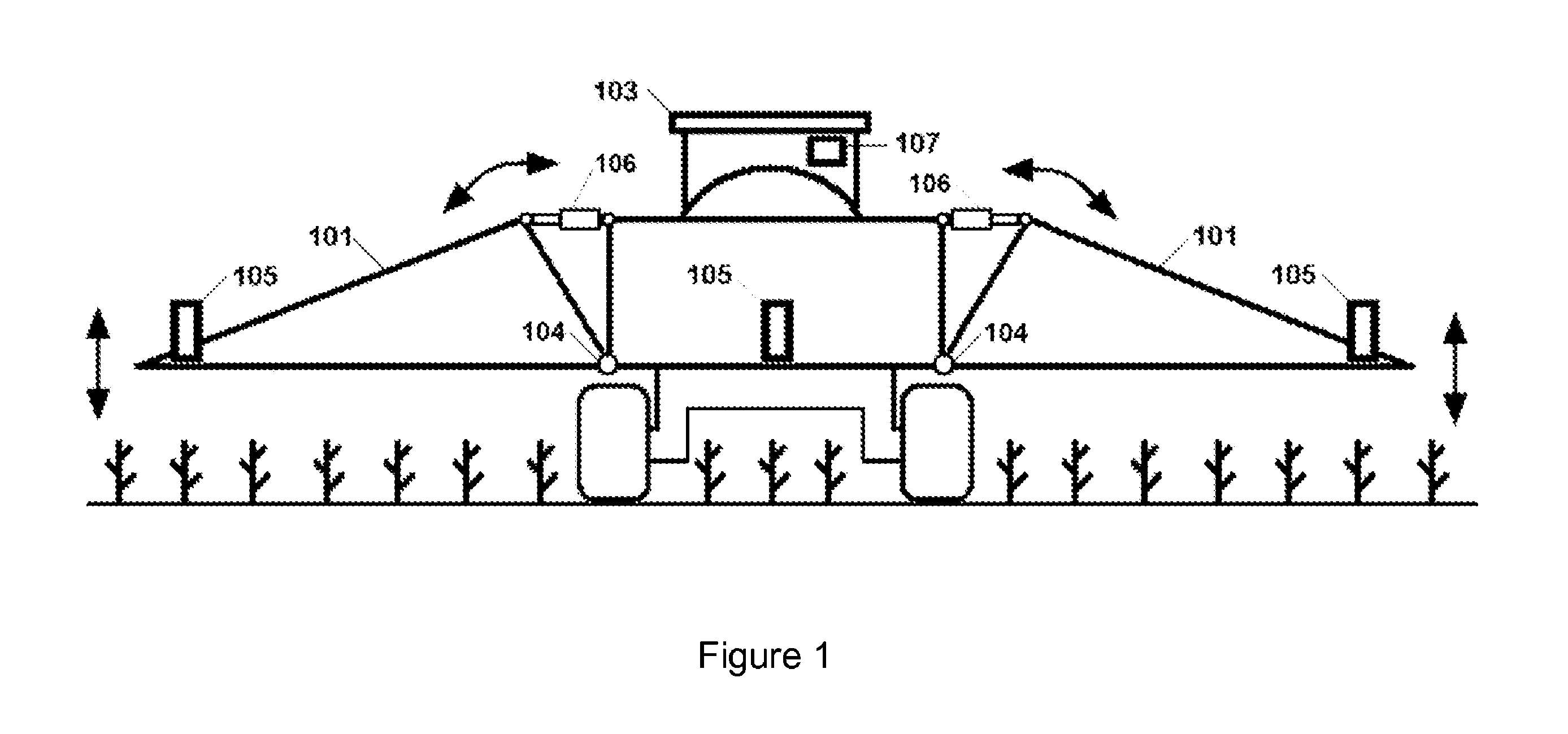
[0024]FIG. 1 shows a tractor unit 103 having variable geometry (VG) sprayer booms 101 arranged on each side of the tractor unit and which are used with and controlled by a control system and method of the present invention. Each of the two VG sprayer booms 101 is mounted to the tractor unit 103 at an end thereof via a well known coupling mechanism such as a hydraulic ram 106 and a pivot 104. The coupling mechanism allows each VG sprayer boom 101 to be tilted (as shown by the arrows in FIG. 1) with respect to the tractor and also to rotate clockwise and anticlockwise about its mounting point with the tractor unit 103. Three ultrasonic sensor modules 105 are mounted on each of the VG sprayer booms 101 in positions in which they are able to project a pulse of ultrasound in a downwards facing cone towards the area directly underneath the VG sprayer boom on which it is mounted. In the preferred embodiment, the ultrasonic sensor modules 105 are mounted on, but in front of, the boom so tha...


PUM


Abstract

A method and apparatus for controlling a height of an agricultural equipment component is provided. An average crop height is determined. In one embodiment, the agricultural equipment component is controlled to maintain a predetermined distance from a current top of crop level. If a current top of crop level cannot be determined, a virtual top of crop level is calculated using the average crop height value. The agricultural equipment component is controlled to maintain a predetermined distance from the virtual top of crop level. In another embodiment, the agricultural equipment component is controlled to maintain a predetermined distance from current ground level. If a current ground level cannot be determined, a virtual ground level is calculated using the average crop height value. The agricultural equipment component is controlled to maintain a predetermined distance from said virtual ground level. An ultrasonic sensor is also provided.

Description

FIELD OF THE INVENTION[0001]This invention relates to a system and method for controlling the height of agricultural equipment components.BACKGROUND OF THE INVENTION[0002]In agriculture, trailed or self propelled units such as sprayers, have booms which are towed behind tractors and are controlled to deliver insecticides and the like to crops through which the tractor drives. Sprayer boom height is typically dynamically positioned in order to maintain a fixed distance between the boom and the crop or soil. Booms are typically rotatable about an axis parallel to the longitudinal axis of the tractor so that they can rotate and remain substantially parallel to the crop even if the tractor drives over sloped ground. Precise control over the height of the boom on which the sprayer nozzles are mounted with respect to the crop is required to avoid damage to the crop by the boom itself as well as to ensure even and proper application of the sprayed chemicals to the crop. The height control ...

Claims


Application Information

Patent Timeline
Patent Type & Authority Patents(United States)
IPC IPC(8): G06F7/70A01D41/14A01M7/00
CPCA01D41/141A01M7/0057A01D41/145
Inventor STRELIOFF, WILLIAMGRIFFITH, JASONSCHNAIDER, JAMESLEE, GORDONHOCKLEY, DEAN
Owner NORAC SYST INT
Why Eureka
Try Eureka