
Power tool

a technology of power tools and tools, applied in the field of power tools, can solve the problems of axial direction of vibration of tool bits, and achieve the effects of reducing the vibration of the tool body, reducing the consumption of power, and reducing the vibration of the dynamic vibration reducer

Active Publication Date: 2014-09-30
MAKITA CORP
View PDF46 Cites 10 Cited by
  • Summary
  • Abstract
  • Description
  • Claims
  • Application Information

AI Technical Summary

Benefits of technology

The invention provides a power tool with a dynamic vibration reducer that reduces vibration during operation. The reducer includes a weight and an elastic element that allow the weight to move in the axial direction of the tool bit. This reducer reduces the number of parts and simplifies the structure of the tool, making it easier to install and disassemble. The reducer can be easily installed and dismantled with the handgrip detached from the housing. The reduction of vibration is achieved by allowing the weight to move smoothly and preventing wear of the sliding surface. The reducer also uses pressure fluctuations in the crank chamber to actively drive the weight, reducing power consumption and simplifying the structure of the tool.

Problems solved by technology

In a power tool in which an operation such as a hammering operation or a hammer drill operation is performed on a workpiece such as concrete by a tool bit, vibration is caused in the axial direction of the tool bit when the tool bit is driven.

Method used


Image

  • Power tool
  • Power tool
  • Power tool

Examples


Embodiment Construction

[0027]Each of the additional features and method steps disclosed above and below may be utilized separately or in conjunction with other features and method steps to provide and manufacture improved power tools and method for using such power tools and devices utilized therein. Representative examples of the present invention, which examples utilized many of these additional features and method steps in conjunction, will now be described in detail with reference to the drawings. This detailed description is merely intended to teach a person skilled in the art further details for practicing preferred aspects of the present teachings and is not intended to limit the scope of the invention. Only the claims define the scope of the claimed invention. Therefore, combinations of features and steps disclosed within the following detailed description may not be necessary to practice the invention in the broadest sense, and are instead taught merely to particularly describe some representativ...


PUM

PropertyMeasurementUnit
weightaaaaaaaaaa
diameteraaaaaaaaaa
pressureaaaaaaaaaa

Abstract

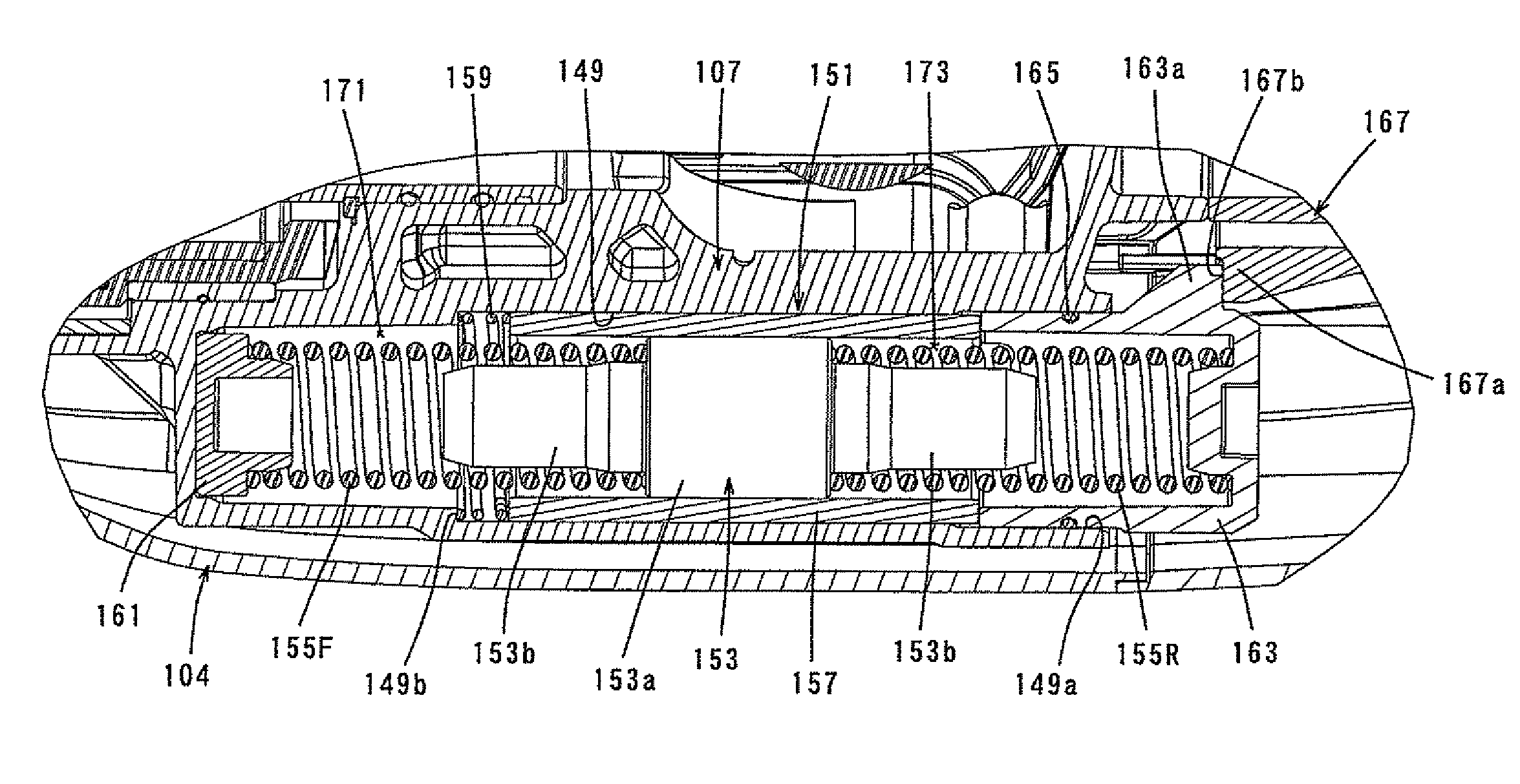
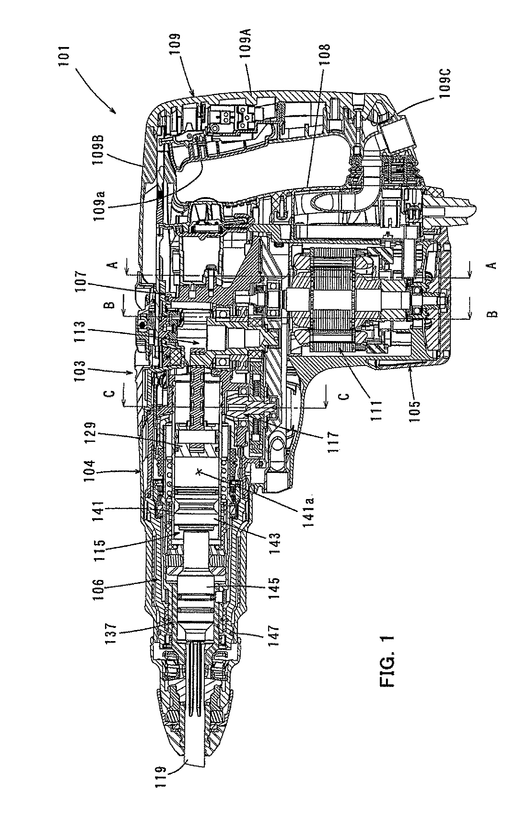
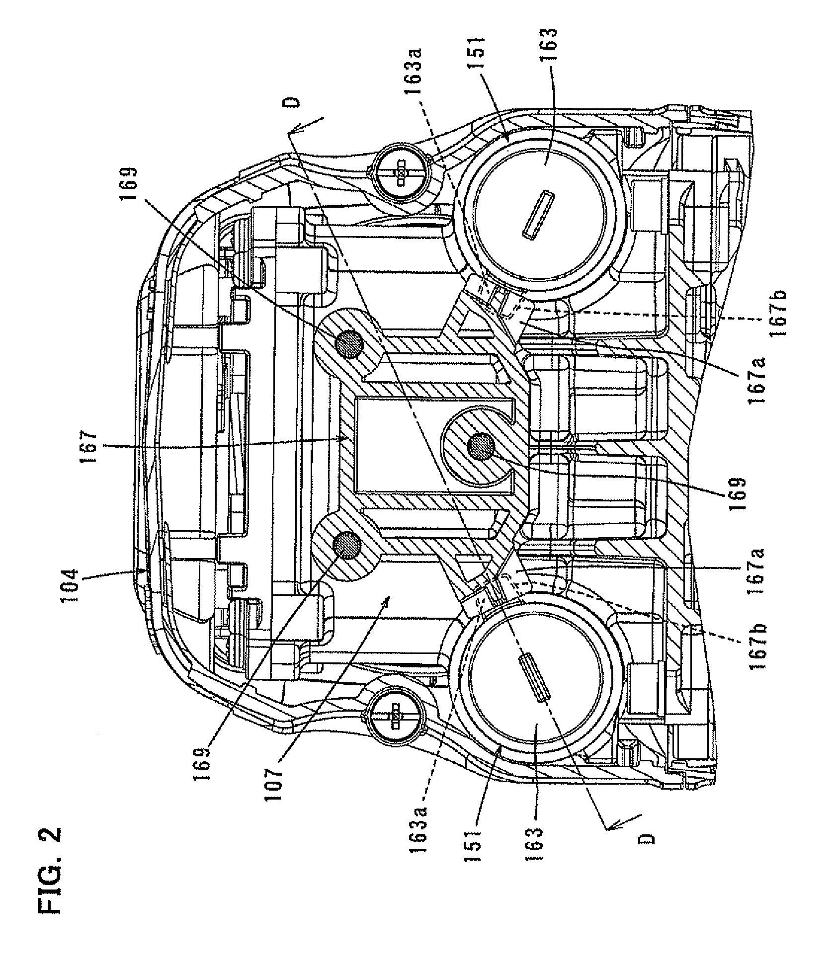
A representative power tool according to the invention performs a predetermined operation on a workpiece at least by axial linear movement of a tool bit 119 coupled to a front end region of a housing 103. The power tool includes driving mechanisms 113, 115 that are housed within the housing 103 and linearly drives the tool bit 119, and a dynamic vibration reducer 151 that has a weight 153 which is allowed to linearly move under a biasing force of an elastic element, and reduces vibration caused during operation, by movement of the weight 153 in the axial direction of the tool bit. A dynamic vibration reducer housing space 149 for housing the weight 153 and the elastic element of the dynamic vibration reducer 151 is integrally formed with the housing 103.

Description

BACKGROUND OF THE INVENTION[0001]1. Field of the Invention[0002]The invention relates to a power tool which performs a predetermined operation on a workpiece at least by axial linear movement of a tool bit.[0003]2. Description of the Related Art[0004]In a power tool in which an operation such as a hammering operation or a hammer drill operation is performed on a workpiece such as concrete by a tool bit, vibration is caused in the axial direction of the tool bit when the tool bit is driven. Therefore, some conventional power tools are provided with a vibration reducing mechanism for reducing vibration caused when the tool bit is driven.[0005]For example, Japanese non-examined laid-open Patent Publication No. 2004-154903 discloses a power tool having a dynamic vibration reducer which serves to reduce vibration caused in the axial direction when the tool bit is driven, and the dynamic vibration reducer includes a dynamic vibration reducer body in the form of a cylindrical element, a we...

Claims


Application Information

Patent Timeline
Patent Type & Authority Patents(United States)
IPC IPC(8): B23D11/00B25D17/24
CPCB25D17/245B25D2250/121B25D2217/0092B25D2250/245B25D2250/065B25D2217/0084
Inventor KAMEGAI, HIKARUFURUSAWA, MASANORI
Owner MAKITA CORP
Learn More