Electrical machine, in particular an electrical generator

a generator and electric motor technology, applied in the field of electric generators, can solve the problems of heating up the stator, inefficiency of electrical machines, and high temperature in the coils of electric machines, and achieve the effects of light electrical machines, reduced material requirements, and compact overhang design

Inactive Publication Date: 2014-09-30
FLENDER GMBH
View PDF16 Cites 8 Cited by
  • Summary
  • Abstract
  • Description
  • Claims
  • Application Information

AI Technical Summary

Benefits of technology

[0015]According to the invention at least one of the end sections of at least one coil of the armature is tilted in a direction away from the armature towards the field magnet arrangement or at least one of the end sections of at least one coil of the field magnet arrangement is tilted in a direction away from the field magnet arrangement towards the armature. This allows overhang length to be reduced, especially of the length of end section without a bent. Accordingly the overhang can designed more compact and the efficiency of the electrical machine is increased. Furthermore, the overhang length of the electrical machine can be reduced, and therefore also the weight of the electrical machine. Also the cooling of the electrical machine can be reduced since joule losses caused in the end-windings are reduced.
[0031]The end section at the second end of the coils could comprise end sections that are tilted with angles between 0° and 90° for facilitating the fabrication. In a preferred embodiment the second end is equipped with end sections tilt by essentially 45° with respect to the body sections.

Problems solved by technology

Inefficiency of electrical machines comes primarily from electromagnetic losses (joule losses, iron losses, .
In permanent magnet generators, for example, these losses mainly come from copper losses in stator conductors, resulting in high temperature in the coils of the electric machine and especially in the end-windings that extend beyond the outer edges of the stator and are surrounded by air.
In the coils and in the end windings joule losses are transformed to thermal energy causing heating up the stator.
For a large armature such as the rotor or stator of a wind turbine, the coil windings are generally quite thick and heavy owing to the physical dimensions of the generator and the high currents induced.
Both of these end section designs which allowing an uncomplicated winding assembly result in an increasing overhang length that results in an undesirable decrease of the efficiency of the machine.

Method used


Image

  • Electrical machine, in particular an electrical generator
  • Electrical machine, in particular an electrical generator
  • Electrical machine, in particular an electrical generator

Examples


Embodiment Construction

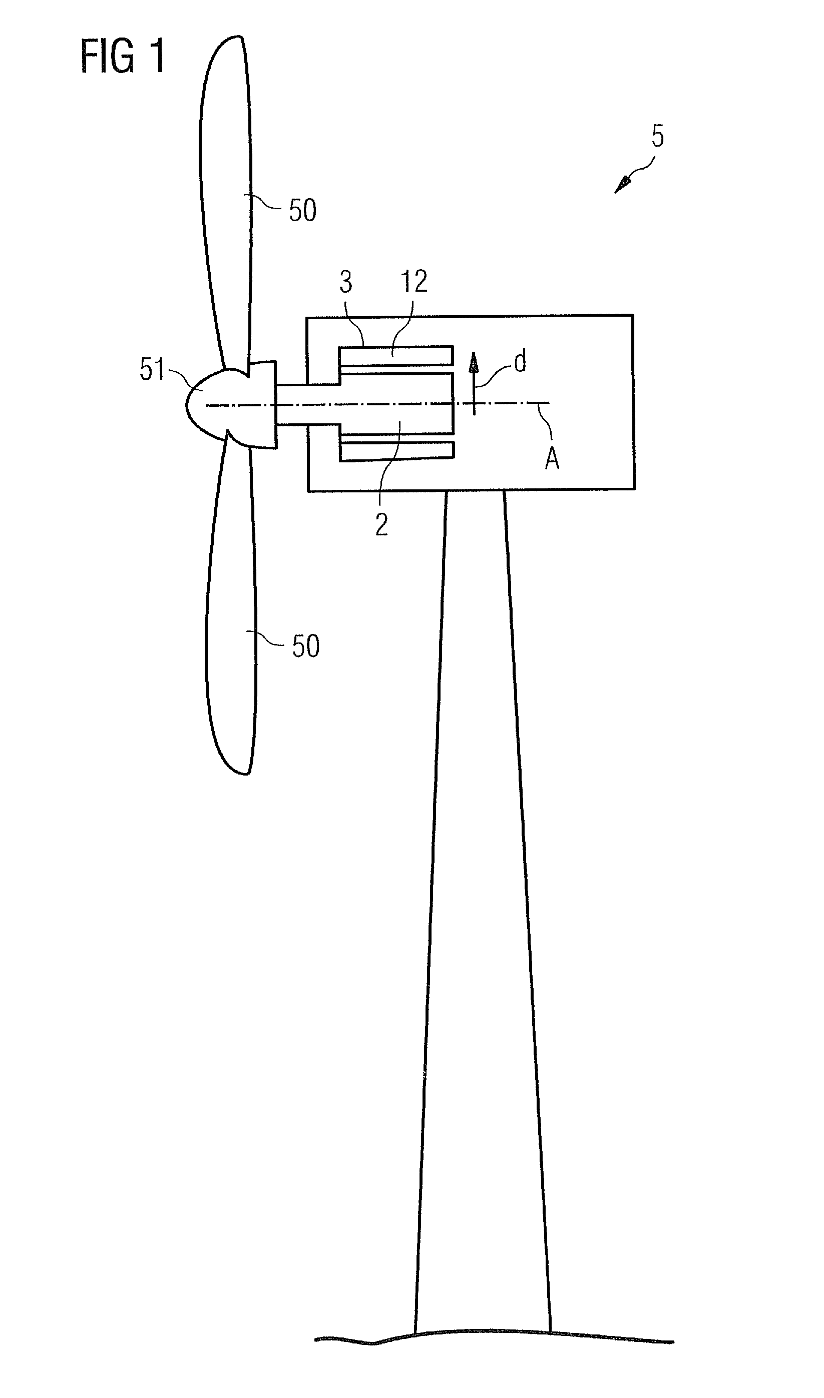
[0042]FIG. 1 shows a very simplified representation of a generator 4 with an internal stator 2 and an external rotor 3 in a wind turbine 5. For the sake of simplicity, only the relevant components are indicated, and other components such as a gearbox, controller, etc. are not shown. Pressure exerted on the blades 50 of the wind turbine 5 cause the hub 51 or spinner to turn about an axis of rotation A, thus causing the external rotor 3 of the generator 4 to rotate. The external rotor 3 is formed by a field magnet arrangement with permanent magnets 12. The internal stator 2 is formed by a fixed armature, whereby about the internal stator 2 a plurality of coils (not shown in the diagram) is wound. The generator 4 operates as an induction generator, with a current being induced in the coils. The principle of operation of such a generator will be clear to the skilled person and need not be described in detail here.

[0043]Because of the large currents (for example in the region of 200-500 ...


PUM


Abstract

An electrical machine includes an armature and at least one field magnet arrangement separated by a gap from each other. The armature and / or the field magnet arrangement include a plurality of coils. Each coil includes conductive body sections. The body sections of the coils are joined electrically by conductive end sections. At least one of the end sections of at least one coil of the armature is tilted in a direction away from the armature towards the field magnet arrangement and / or at least one of the end sections of at least one coil of the field magnet arrangement is tilted in a direction away from the field magnet arrangement towards the armature. The electrical machine may be used in a wind turbine to generate electrical power.

Description

CROSS REFERENCE TO RELATED APPLICATIONS[0001]This application claims priority of European Patent Office application No. 11156219.5 EP filed Feb. 28, 2011. All of the applications are incorporated by reference herein in their entirety.FIELD OF INVENTION[0002]The invention concerns an electrical machine, in particular an electrical generator. The invention further concerns an armature and / or field magnet arrangement for such an electrical machine, a wind turbine with such an electrical machine and the use of such an electrical machine as generator.BACKGROUND OF INVENTION[0003]Inefficiency of electrical machines comes primarily from electromagnetic losses (joule losses, iron losses, . . . ) in which energy is dissipated as heat. In permanent magnet generators, for example, these losses mainly come from copper losses in stator conductors, resulting in high temperature in the coils of the electric machine and especially in the end-windings that extend beyond the outer edges of the stator...

Claims


Application Information

Patent Timeline
Patent Type & Authority Patents(United States)
IPC IPC(8): H02K3/12H02K7/18
CPCH02K3/12Y02E10/725H02K7/1838H02K2213/12Y02E10/72
Inventor LE, BESNERAIS, JEAN
Owner FLENDER GMBH
Why Eureka
Try Eureka