Antenna device and communication device

a communication device and antenna technology, applied in the direction of loop antennas with ferromagnetic cores, instruments, inductances, etc., can solve the problems of difficult mounting of antenna structures, inability to easily secure space for antenna structures described in patent document 1, and deterioration of the efficiency of receiving magnetic fields, so as to achieve efficient attraction, maintain communication characteristics, and reduce the size and thickness of the electronic device housing

Active Publication Date: 2014-09-30
DEXERIALS CORP
View PDF11 Cites 19 Cited by
  • Summary
  • Abstract
  • Description
  • Claims
  • Application Information

AI Technical Summary

Benefits of technology

[0012]The present invention has been proposed in consideration of the above circumstances, and has as its object to provide an antenna device and a communication device that can reduce a housing of an electronic device in size and thickness when the antenna device and the communication device are built in the electronic device while keeping communication characteristics.
[0015]According to the present invention, the antenna coil and the magnetic sheet are superposed on each other to satisfy at least one of the arrangement conditions including the arrangement condition in which the magnetic sheet is located on the transmitter side of the antenna coil on the center side of the housing surface and the arrangement condition in which the antenna coil is located on the transmitter side of the magnetic sheet on the outer periphery side of the housing surface. When the magnetic sheet is arranged as described above, according to the present invention, magnetic fluxes generated on the outer peripheral portion of the housing surface of the electronic device facing the transmitter can be efficiently attracted to the antenna coil to make it possible to reduce the housing of the electronic device in size and thickness when the antenna device or the communication device is built in the electronic device by arranging the antenna coil is arranged on the outer peripheral portion while maintaining communication characteristics.

Problems solved by technology

For this reason, in an antenna using a normal loop coil, efficiency of receiving a magnetic field is deteriorated.
Thus, in a relatively thin mobile phone, the structure is difficult to be mounted.
For this reason, a space for the antenna structure described in Patent Document 1 cannot be easily secured.

Method used


Image

  • Antenna device and communication device
  • Antenna device and communication device
  • Antenna device and communication device

Examples


first embodiment

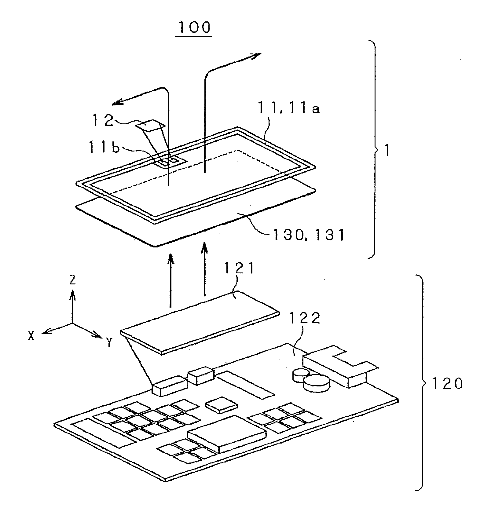
[0060]In the wireless communication system 100 having the above configuration, the configuration of the communication device 1 according to the first example will be described below as the first embodiment.

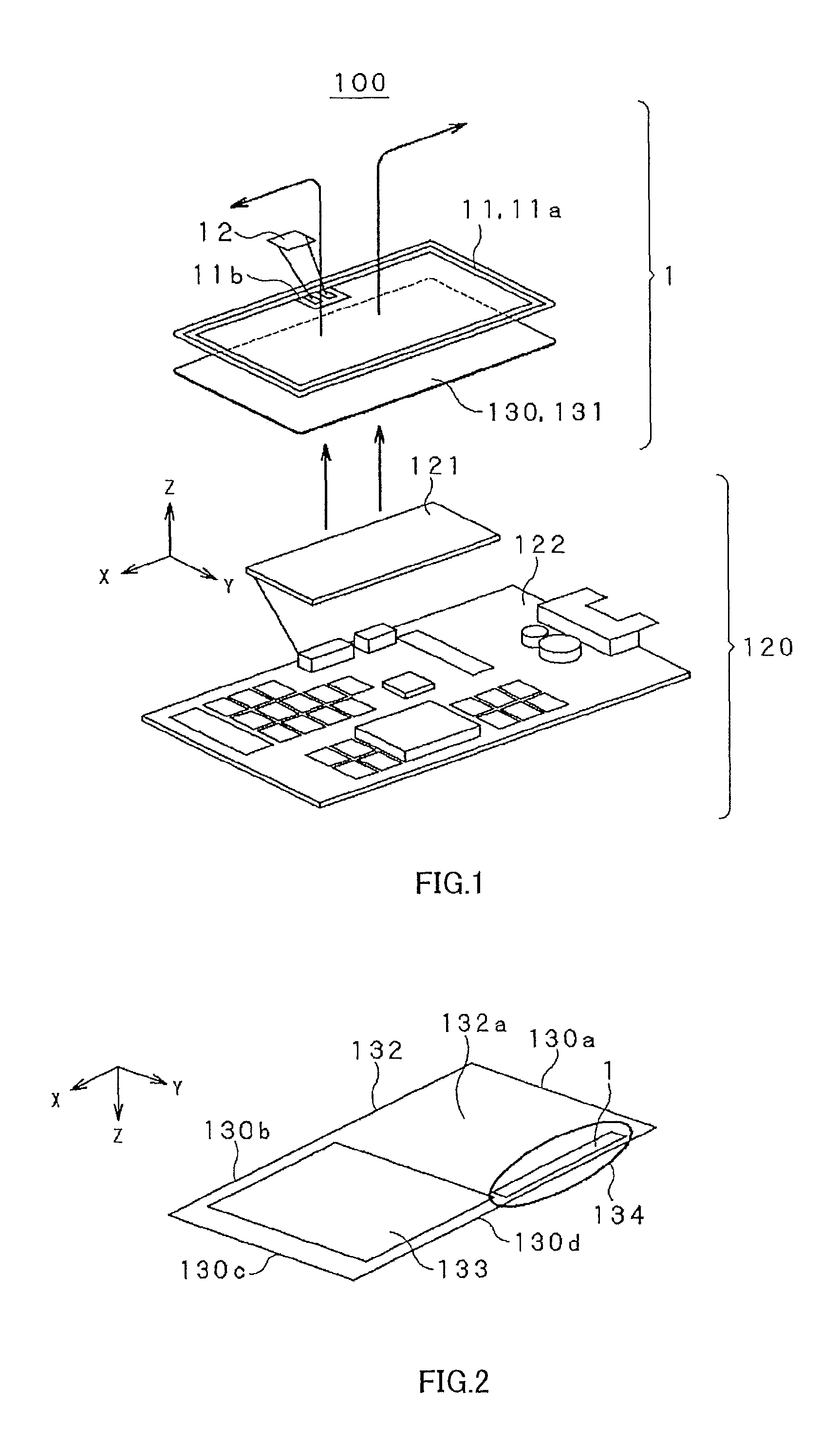
[0061]The communication device 1 according to the first example, in terms of realization of reductions in size and thickness of an electronic device such as the mobile phone 130 when the communication device 1 is built in the electronic device while maintaining communication characteristics between the reader / writer 120 and the communication device 1, for example, is arranged on a circuit board 132 in the housing 131 of the mobile phone 130 on a Z-y plane of the three-dimensional orthogonal coordinate system xyz. In FIG. 2, it is assumed that a magnetic sheet 133 to cover a battery pack to drive the mobile phone 130 is arranged in a partial region of the circuit board 132 in the housing 131 of the mobile phone 130

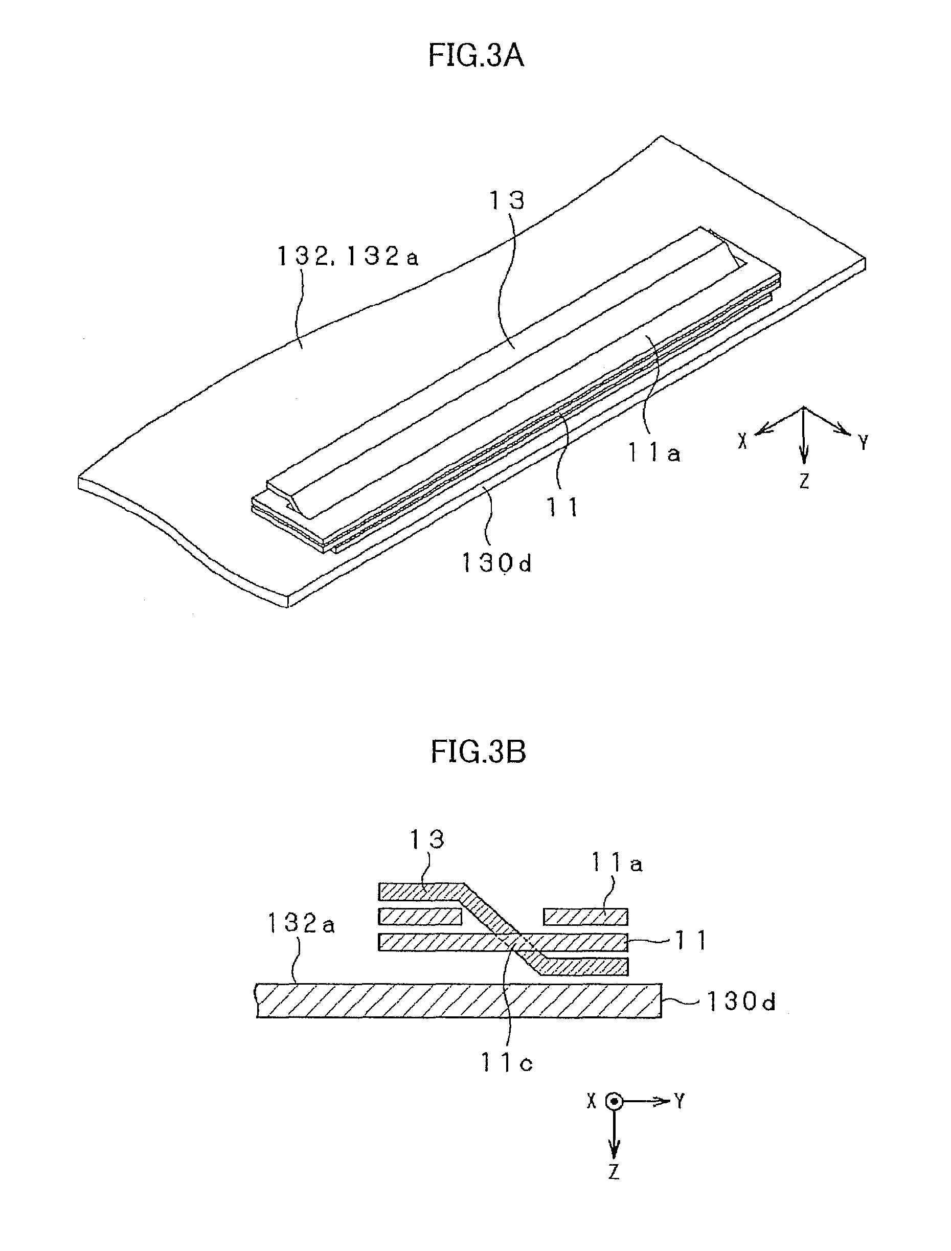
[0062]The antenna coil 11a of the communication device 1 is preferab...

second embodiment

[0097]A communication device to which the present invention is applied, as a second embodiment, for example, as shown in FIG. 14A, a conductive plate having a conductivity higher than that of a metal body constituting a housing is arranged on the housing side of the electronic device to make it possible to realize more preferable communication characteristics.

[0098]That is, a communication device 5 according to a fifth example shown in FIG. 14A, as in the first example, a magnetic sheet 53 is inserted into a center portion 51c of an antenna coil 51a formed on the antenna substrate 51. Furthermore, the communication device 5 according to the fifth example, as shown in FIG. 14B, includes a plate-shaped conductive plate 54 superposed on the circuit board 132 serving as a metal plate arranged inside the housing 131 to entirely cover the outer peripheral portion of the antenna coil 11a. More specifically, in the communication device 5, the conductive plate 54 is arranged to be in contact...

third embodiment

[0126]As the third embodiment, a communication device according to a sixth example to which the present invention is applied employs a structure in which an antenna coil and a magnetic sheet are superposed on each other to have almost the same plane on both the surfaces on a reader / writer side and a substrate side so as to realize a small thickness and preferable communication characteristics.

[0127]FIG. 25A is a diagram showing a positional relationship between a communication device 6 according to the sixth example and the reader / writer 120, and FIG. 25B is a sectional view of an antenna substrate 61 according to the communication device 6 according to the sixth example.

[0128]More specifically, the communication device 6, as shown in FIG. 25B, at a center portion 61c where a magnetic sheet 63 is inserted into a center portion of a antenna coil 61a formed on the antenna substrate 61, a step portion 61d is formed on the antenna substrate 61. In the communication device 6, a step port...


PUM


Abstract

The present invention provides a communication device that can reduce a housing of an electronic device in size and thickness when the communication device is built in the electronic device. The communication device includes: an antenna coil (11a) arranged on an outer peripheral portion (134) of a housing (131) surface facing a reader / writer (120) of a mobile phone (130); a magnetic sheet (13) that attracts a magnetic field transmitted from the reader / writer (120) to the antenna coil (11a); and a communication processing unit (12) that is driven by a current flowing in the antenna coil (11a) and performs communication with the reader / writer (120), wherein the magnetic sheet (13) is arranged on the reader / writer (120) side of the antenna coil (11a) at a center portion (132a), and the antenna coil (11a) is arranged on the reader / writer (120) side on an outer periphery (130d) side.

Description

FIELD OF THE INVENTION[0001]This present invention relates to an antenna device and a communication device that are built in an electronic device and can perform communication by receiving a magnetic field transmitted from a transmitter.CROSS-REFERENCE TO RELATED APPLICATIONS[0002]The present application asserts priority rights based on JP Patent Application 2010-082037 filed in Japan on Mar. 31, 2010 and JP Patent Application 2011-070666 filed in Japan on Mar. 28, 2011. The total contents of disclosure of the Patent Application of the senior filing date are to be incorporated by reference in to the present Application.BACKGROUND OF THE INVENTION[0003]An electronic device such as a mobile phone uses an antenna module for RFID (Radio Frequency Identification) to mount a near field contactless communication function thereon.[0004]The antenna module performs communication with an antenna coil mounted on a transmitter such as a reader / writer by using inductive coupling. More specificall...

Claims


Application Information

Patent Timeline
Patent Type & Authority Patents(United States)
IPC IPC(8): H04B5/00H01Q1/22H01Q1/24H01Q7/00
CPCH01Q1/243H01Q1/2225H01Q7/00H01Q1/24H01Q1/2208H01Q1/42H01Q1/2266G06K19/077H01Q7/06
Inventor ORIHARA, KATSUHISAIKEDA, YOSHITOSAITO, NORIOSUGITA, SATORU
Owner DEXERIALS CORP
Why Eureka
Try Eureka