Semantic translation of stateflow diagrams into input/output extended finite automata and automated test generation for simulink/stateflow diagrams

a stateflow diagram and stateflow translation technology, applied in the field of semantic translation of diagrams, can solve problems such as not providing a model that makes it amenable to formal analysis

Active Publication Date: 2014-09-30
IOWA STATE UNIV RES FOUND
View PDF5 Cites 10 Cited by
  • Summary
  • Abstract
  • Description
  • Claims
  • Application Information

AI Technical Summary

Benefits of technology

[0008]It is a further object, feature, or advantage of the present invention to provide a semantic translation approach which is recursive.
[0009]It is a still further object, feature, or advantage of the present invention to provide a semantic translation approach which is amenable to automated test generation and verification.
[0010]It is a still further object, feature, or advantage of the present invention to provide a semantic translation approach which has no special restriction on the types of blocks.
[0011]It is a still further object, feature, or advantage of the present invention to provide a semantic translation approach which is sound and complete.
[0012]It is a still further object, feature, or advantage of the present invention to translate a chart comprising event-driven blocks, such as a Stateflow chart into an I / O-EFA that preserves the discrete behaviors.
[0013]A still further object, feature, or advantage of the present invention is to provide an automatic test generation approach for Simulink / Stateflow based on its translation to Input / Output Extended Finite Automata (I / O-EFA).

Problems solved by technology

Although Simulink / Stateflow is designed for the simulation of the designs, it does not provide a model that makes it amenable for formal analysis such as verification and validation.
The test generation problem requires identifying the executable paths of the I / O-EFA model and also generating a test input for those paths.

Method used


Image

  • Semantic translation of stateflow diagrams into input/output extended finite automata and automated test generation for simulink/stateflow diagrams
  • Semantic translation of stateflow diagrams into input/output extended finite automata and automated test generation for simulink/stateflow diagrams
  • Semantic translation of stateflow diagrams into input/output extended finite automata and automated test generation for simulink/stateflow diagrams

Examples


example 1

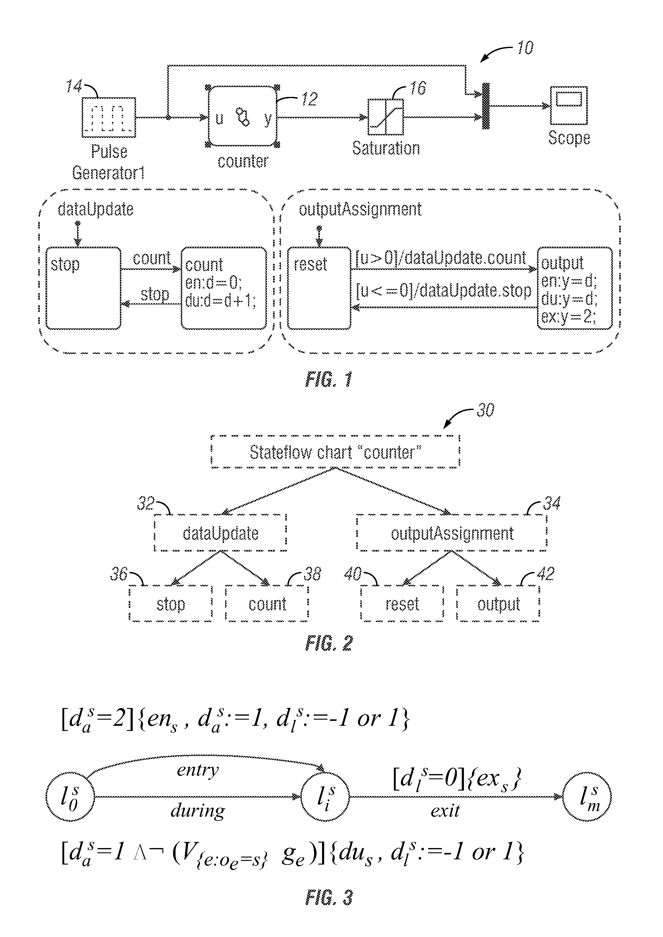
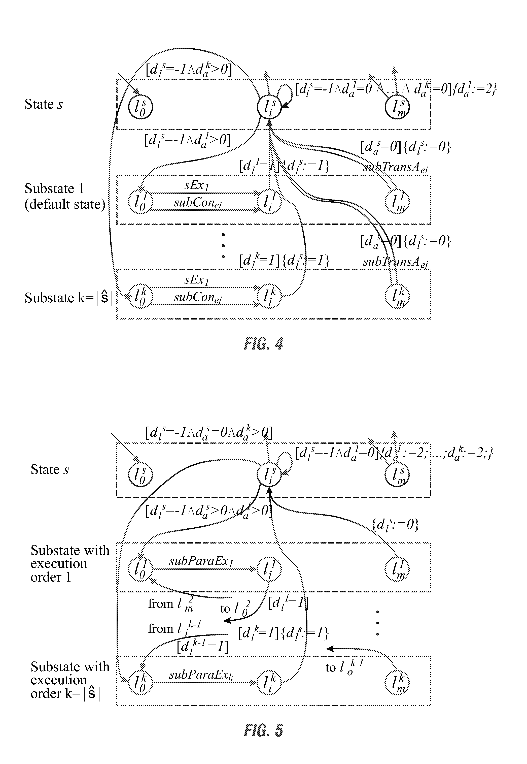
[0154]Consider the counter system of FIG. 1. It can be translated into an I / O-EFA model as follows:[0155]1. Modeling states: We first construct atomic model for each of the seven states (including the Stateflow root) of FIG. 2.[0156]2. Modeling state hierarchy: We apply OR Complex State Composition Rule (Algorithm 2) on the models obtained in step 1 of the two bottom-level OR complex states, and AND Complex State Composition Rule (Algorithm 3) on models obtained in step 1 of the top-level AND complex state.[0157]3. Modeling local events: Each edge in the model obtained in step 2 containing the event “count” or “stop” is replaced with a pair of edges to connect the source state “outputAssignment” and the destination state “dataUpdate”, in either direction. At the same time the evaluation of “count” (resp., “stop”) is modified to dev1=1 (resp., dev2=1).[0158]4. Obtaining final model: The model obtained in step 3 is augmented by applying Algorithm 5 to obtain a final model (this step i...

example 2

[0160]The simulation result comparison between the I / O-EFA model of the counter (see FIG. 8) and the original counter system (see FIG. 1) is shown in FIG. 9. The simulation (using Intel Core 2 Duo P8400 2.27 GHz, 2 GB RAM) time is 4 seconds with sampling period of 0.03 seconds, and the results are consistent with the behaviors of the counter.

example 3

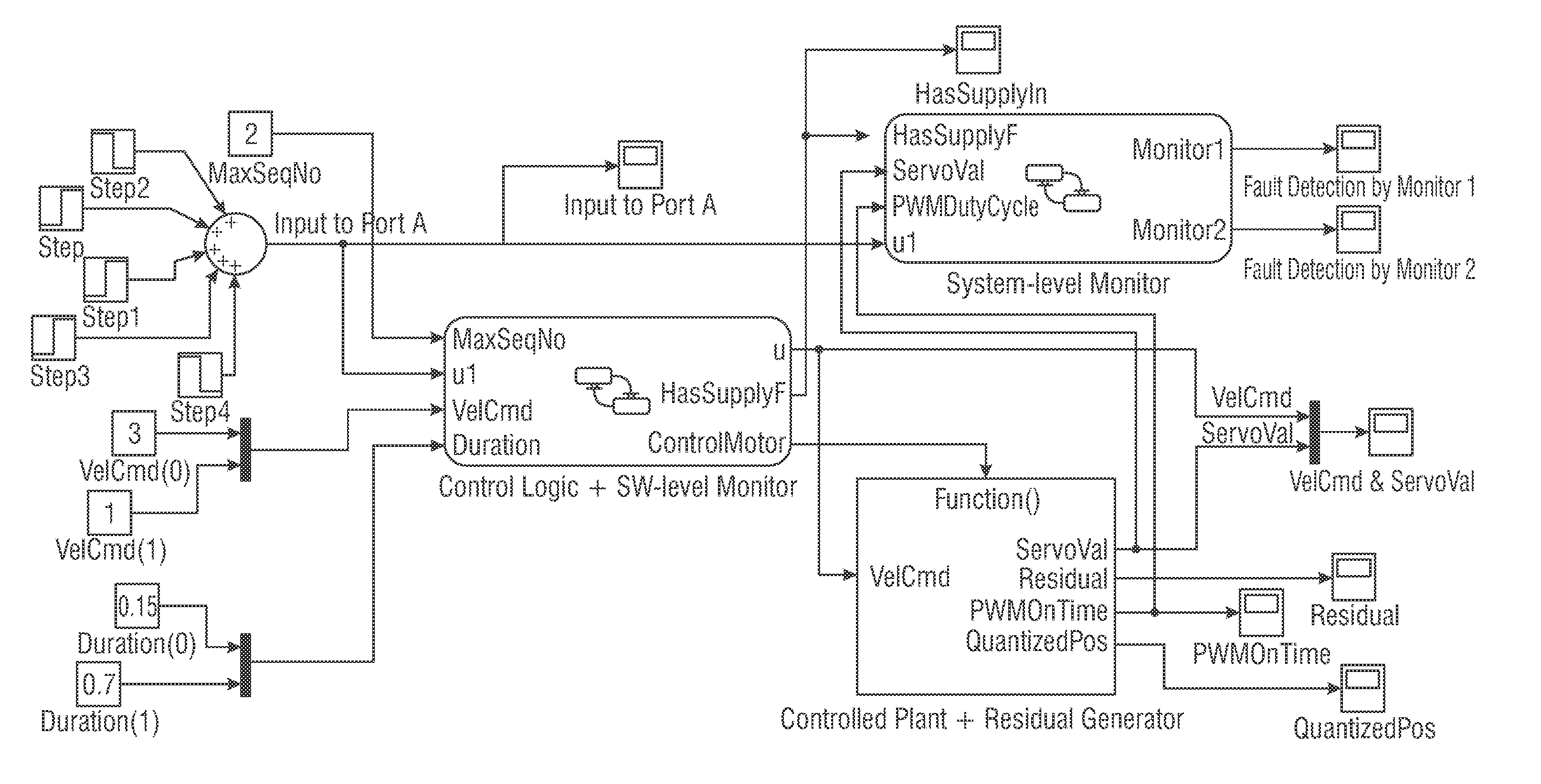
[0161]This example is of a servo velocity control system consisting of a controller, a fault monitor (both written in Stateflow), and a motor (written in Simulink). The Simulink / Stateflow diagram of the servo velocity control system is translated by our translation tool. The CPU time (using Intel Core 2 Duo P8400 2.27 GHz, 2 GB RAM) for the translation is 45.1 seconds and the translated model has 382 locations and 646 edges. The simulation result of the translated model (shown in FIG. 11) is identical to the discrete behaviors of the original Simulink / Stateflow model.

VIII. Introduction to Model-based Automatic Test Generation for Simulink / Stateflow Using Extended Finite Automaton

[0162]As previously explained, Simulink / Stateflow [4] is a model-based development tool, which is widely used in many industrial domains, such as power systems, nuclear plants, aircraft, and automotives. Code generators are used within the Simulink / Stateflow to automatically generate the embedded software fo...


PUM


Abstract

A method of translation of a chart associated with a graphical modeling environment into an input/output-extended finite automata (I/O-EFA) model is provided. The method includes receiving a representation of the chart and processing the representation of the chart with a computing device by (a) representing atomic models for each individual state of the chart, (b) applying composition rules to interconnect the atomic models while preserving state execution and transition behaviors to obtain the I/O-EFA model.

Description

CROSS-REFERENCE TO RELATED APPLICATIONS[0001]This application is a Continuation-in-Part of U.S. Ser. No. 13 / 165,907 filed Jun. 22, 2011 which claims priority under 35 U.S.C. §119 of a provisional application Ser. No. 61 / 357,568 filed Jun. 23, 2010, all of which are hereby incorporated by reference in its entirety.GRANT REFERENCE[0002]This invention was made with government support under Grant No. NSF-CCF-0811541 awarded by the National Science Foundation. The government has certain rights in the invention.FIELD OF THE INVENTION[0003]The present invention relates to a semantic translation approach for diagrams associated with graphical modeling and simulation environments or tools. The semantic translation generates a model which may be used for further analysis such as test generation and formal verification.BACKGROUND OF THE INVENTION[0004]Graphical modeling and simulation environments or tools allow users to construct and analyze models of processes or systems using diagrams. Ther...

Claims


Application Information

Patent Timeline
Patent Type & Authority Patents(United States)
IPC IPC(8): G06F17/50
CPCG06F9/444G06F8/34G06F9/4498
Inventor KUMAR, RATNESHLI, MENG
Owner IOWA STATE UNIV RES FOUND
Why Eureka
Try Eureka