Respiration humidifier

a humidifier and reservoir technology, applied in the field of reservoir humidifiers, can solve the problems of inability to meet the needs of homogeneous mixing of air and vapor, inability to achieve sufficient humidification effect, and inability to completely cover the disadvantageous, etc., to achieve the effect of low design effort, high evaporation capacity and low cos

Inactive Publication Date: 2014-10-07
DRAGERWERK AG
View PDF18 Cites 18 Cited by
  • Summary
  • Abstract
  • Description
  • Claims
  • Application Information

AI Technical Summary

Benefits of technology

[0010]The object of the present invention is therefore to make available a respiration humidifier, in which high evaporation capacity can be reached with a homogeneous air-vapor mixture at a low design effort. Furthermore, splash water shall be avoided in the humidifying chamber and the respiration humidifier shall be able to be manufactured at a low cost.

Problems solved by technology

The vapor cannot disadvantageously be taken up completely by the breathing air because of the limited contact surface between the water and the air, on the one hand, and the high velocity of flow of the breathing air or the short residence time of the breathing air in the humidifying chamber, on the other hand, so that sufficient humidifying effect is not guaranteed.
Furthermore, the necessary homogeneous mixing of the air and vapor is not possible in a satisfactory manner.
The relatively small cross-sectional areas of the breathing air channels formed by the guide body in the humidifying chamber lead to high flow velocities and hence to very short residence times, so that the uptake of vapor by the breathing air at the water surface is very limited.
These baffle plates cause a disadvantageous additional flow resistance for the breathing air and require an additional design effort and manufacturing cost.
The vertical orientation of the water-absorbing material in the humidifying chamber in the upper area of the absorbing material disadvantageously brings about a low degree of saturation with water in both class-forming documents because the path over which the water must rise in this area is long.
Furthermore, there is no protection against splashing of water caused by the breathing air flowing in, because only a small percentage of the surface of the water is covered by the absorbing material.
The geometry of the absorbing material causes an unfavorable air flow, which fails to guarantee a reliable homogeneous mixing of the air and vapor.

Method used


Image

  • Respiration humidifier
  • Respiration humidifier
  • Respiration humidifier

Examples


Embodiment Construction

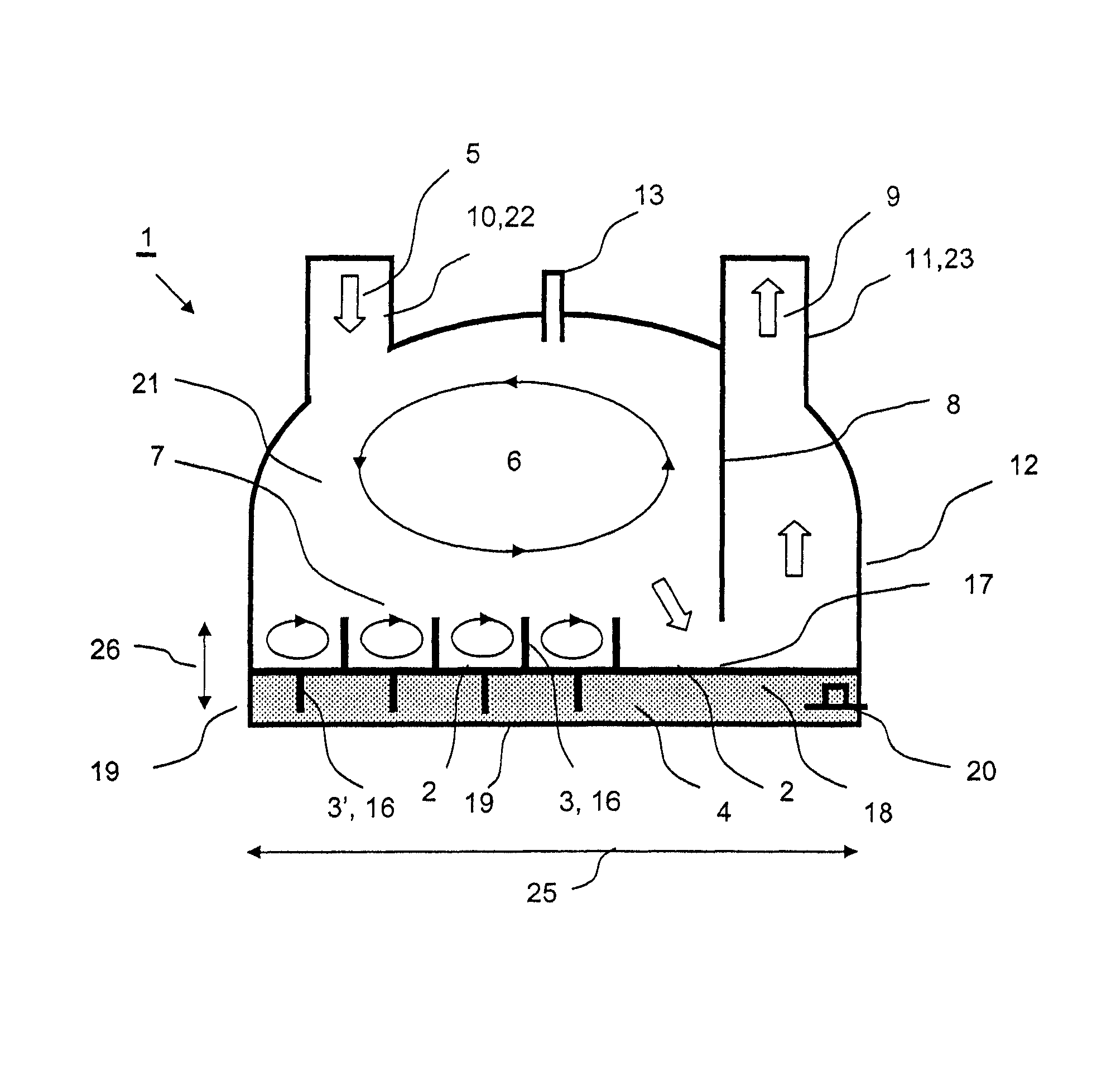
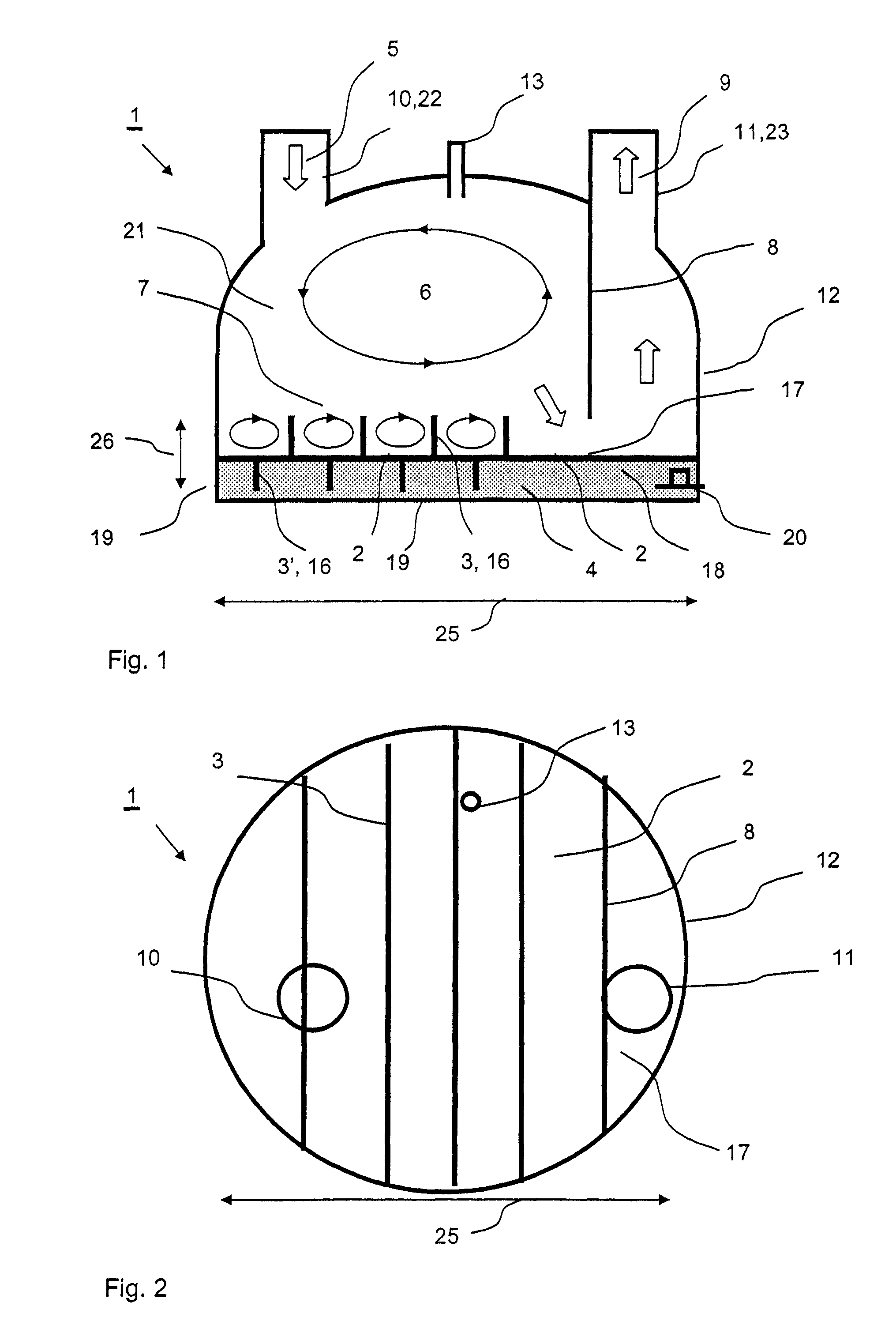
[0034]Referring to the drawings in particular, FIG. 1 shows a schematic vertical section of a respiration humidifier 1 for humidifying and heating breathing air 5 to be humidified for the artificial respiration of patients. A humidifying chamber 21 is enclosed by a housing 12. The top side of the housing 12 is provided with an inlet means 10 designed as an inlet opening 22 for introducing breathing air 5 to be humidified into the humidifying chamber 21 and with an outlet means 11 designed as an outlet opening 23 for drawing off humidified breathing air 9 from the humidifying chamber 21. The breathing air 5 to be humidified flows through the inlet opening 22 into the humidifying chamber 21 and is again discharged as humidified breathing air 9 from the humidifying chamber 21 after taking up moisture or water vapor. In addition, a water inlet opening 13 for introducing water 4 into the humidifying chamber 21 is present. The housing 12 forms on the underside of the humidifying chamber 2...


PUM


Abstract

A respiration humidifier (1), including a humidifying chamber (21), an inlet (10) for feeding breathing air (5) to be humidified into the humidifying chamber (21), an outlet (11) for releasing the humidified breathing air (9) from the humidifying chamber (21), a bottom (19) limiting the humidifying chamber (21) for receiving water (18) to be evaporated, water (4), which is received by the bottom (19) in the humidifying chamber (21) and is to be evaporated for humidifying the breathing air (5) and at least one distributor (2) with capillary and / or suction action, which is arranged in the humidifying chamber (21) such that this is in contact with the water (4) to take up water (4) in the distributor (2) and is in contact with the breathing air in the humidifying chamber (21) for evaporating the water (4) taken up on the surface of the distributor (2) into the breathing air (5). The respiration humidifier allows a high evaporating capacity to be reached with homogeneous air-vapor mixture at a low design effort. Furthermore, splash water is avoided in the humidifying chamber and the respiration humidifier is able to be manufactured at a low cost. This object is accomplished by the at least one distributor (2) covering at least 50% of the surface of the water (4).

Description

CROSS REFERENCE TO RELATED APPLICATIONS[0001]This application claims the benefit of priority under 35 U.S.C. §119 of German Patent Application DE 10 2007 037 458.7 filed Aug. 8, 2007, the entire contents of which are incorporated herein by reference.FIELD OF THE INVENTION[0002]The present invention pertains to a respiration humidifier.BACKGROUND OF THE INVENTION[0003]The human nose acts as a means of actively heating and humidifying the breathing air under physiological conditions. However, the artificial respiration of patients requires that the nose be bypassed and the breathing air is sent directly into the human trachea with a tube (flexible tube). The inspired air must therefore be humidified and optionally also heated to physiological values in order to maintain the lung function in case of artificial respiration.[0004]Prior-art respiration humidifiers have a humidifying chamber as a cavity with an inlet opening and with an outlet opening for the breathing air. Water to be eva...

Claims


Application Information

Patent Timeline
Patent Type & Authority Patents(United States)
IPC IPC(8): A61M16/16A61M16/10
CPCA61M16/16A61M16/109A61M16/1075A61M16/161
Inventor KUO, ARTHURBRIEGER, KAIOTTE, TOBIAS
Owner DRAGERWERK AG
Why Eureka
Try Eureka