Rotating stall detection using optical measurement of blade untwist

a technology of optical measurement and rotating stall, which is applied in the direction of efficient propulsion technologies, machines/engines, instruments, etc., can solve problems such as the potential for subsequent compressor stall, and achieve the effect of preventing major engine mishaps and increasing engine performan

Active Publication Date: 2014-10-07
PRIME PHOTONICS LC
View PDF21 Cites 0 Cited by
  • Summary
  • Abstract
  • Description
  • Claims
  • Application Information

AI Technical Summary

Benefits of technology

[0013]Embodiments of the present invention relate to the development and implementation of a real time, uncooled, high temperature early detection mechanism for compressor stall as a key enabler in the prevention of major engine mishaps, and ultimately in the increase of engine performance.
[0014]One principle of the invention is the ability to detect a change in the twist profile of a blade by comparing the twist profile of one blade to that of previous twist profiles of the same blade or other blades. Making this comparison with data obtained during the same or previous revolutions of the rotor instead of with a fixed pre-determined value is a more accurate way of identifying a blade stall and thus predicting the onset of compressor stall.
[0017]Specifically, an object of the present invention includes one or more light source (also referred to as an optical source) and a plurality of optical fibers arranged to provide a line probe operably configured for transmitting light from the light source(s), receiving light reflected from one or more blades passing through the transmitted light, and determining the intensity of the reflected light. Optionally, the light transmitted and / or reflected can pass through a lens for providing more or less focused light for a particular application. Further, a hermetic window can be used to protect the optical components from the blades or other parts of the compressor.
[0018]Rotating stall detection systems of the invention can incorporate the capabilities of any type of sensor technology. Sensors used in preferred embodiments are optical sensors. For example, the technology disclosed in U.S. Pat. No. 8,164,761 issued Apr. 24, 2012 and entitled “Differential Focus Blade Clearance Probe and Methods for Using Same,” and disclosed in US Published Application No. 2010 / 0177299, entitled “Differential Focus Blade Clearance Probe,” published Jul. 15, 2010, would provide a sufficient platform for obtaining the needed data for determining stall onset according to methods of the invention. Such sensors are capable of providing real time measurements of blade tip clearance, time of arrival, blade speed, detection of high cycle fatigue including blade motion, and detection of foreign object damage (FOD) at uncooled temperatures of up to 510° C. (950° F.).

Problems solved by technology

As the spacing between receive signals within the twist profile is shortened, untwist of the blade (caused by unloading) occurs and when unloaded this indicates stall of that blade and the potential for subsequent compressor stall.

Method used


Image

  • Rotating stall detection using optical measurement of blade untwist
  • Rotating stall detection using optical measurement of blade untwist
  • Rotating stall detection using optical measurement of blade untwist

Examples


Embodiment Construction

[0038]Reference will now be made in detail to various exemplary embodiments of the invention. It is to be understood that the following discussion of exemplary embodiments is not intended as a limitation on the invention. Rather, the following discussion is provided to give the reader a more detailed understanding of certain aspects and features of the invention.

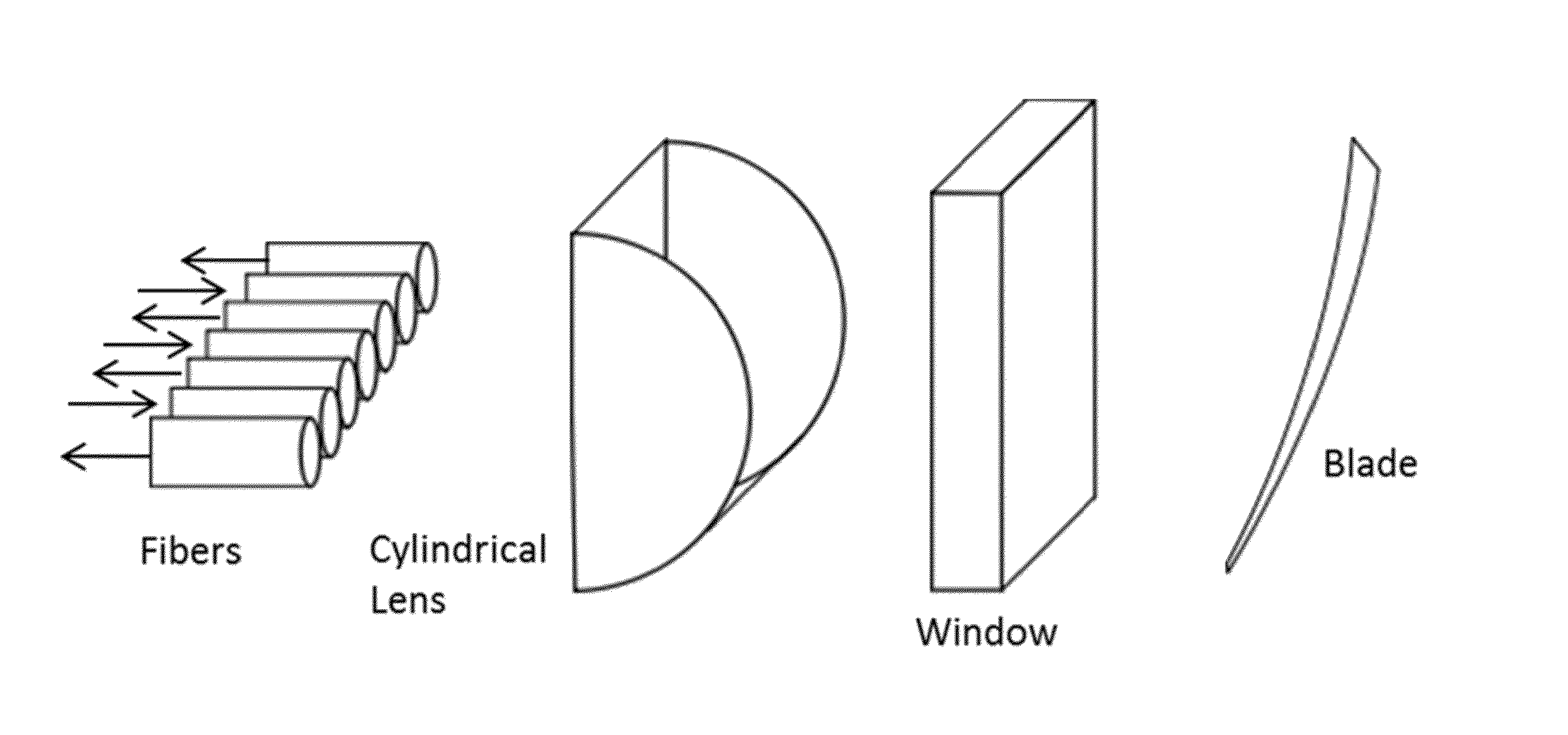
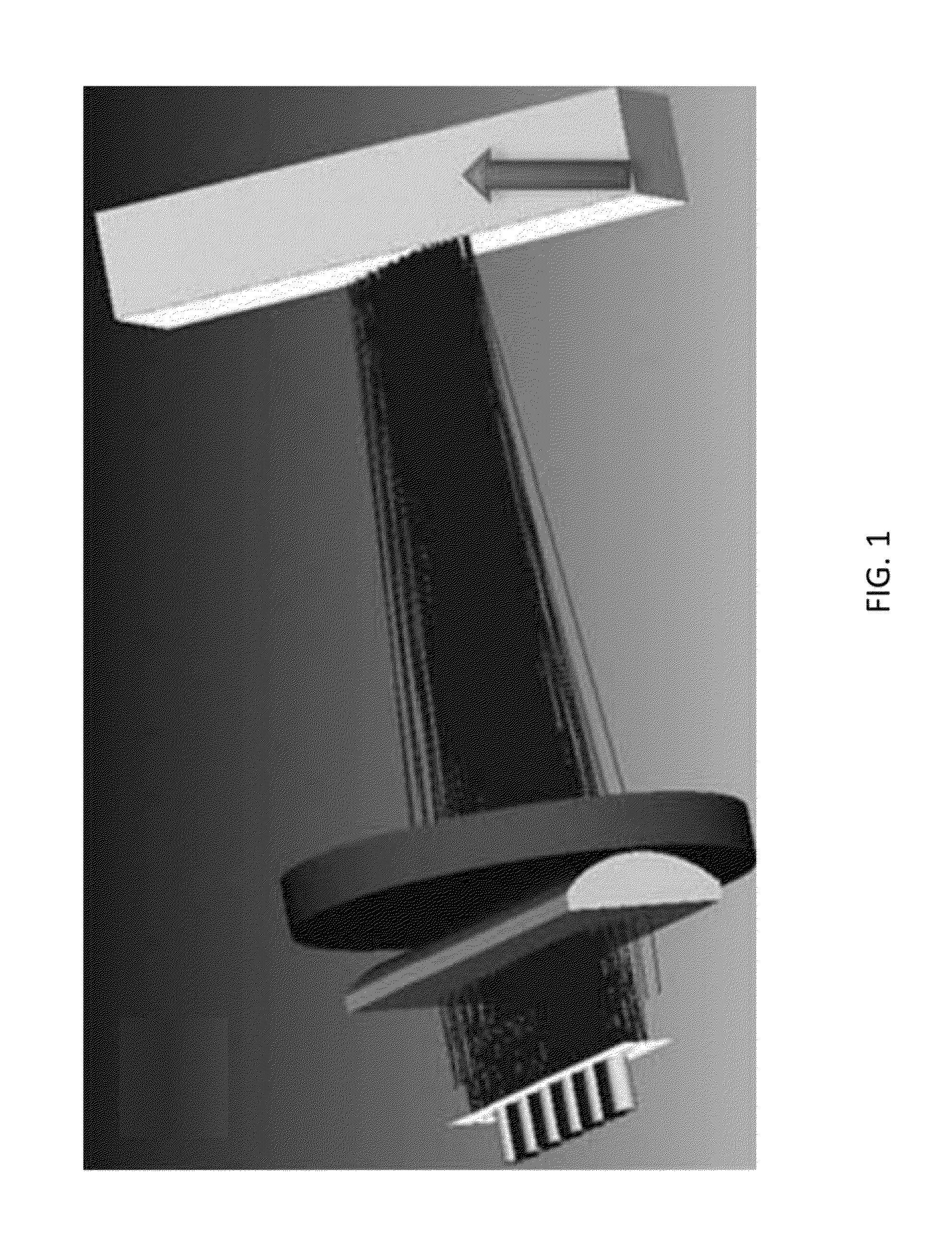
[0039]A representative system of the invention is shown in FIG. 1. Provided in FIG. 1 is a schematic diagram illustrating an embodiment of a fiber-optic based rotating stall detection system (RSDS). The system generally comprises a line of optical fibers behind a cylindrical lens, optionally shielded from the engine environment by a hermetic window, where every other fiber either transmits light toward or receives reflected light from a blade moving through the optical path of the probe. In embodiments of the methods, systems, and devices of the invention, the line probe can comprise a row of optical fibers, wherein one or m...


PUM

PropertyMeasurementUnit
temperaturesaaaaaaaaaa
angleaaaaaaaaaa
angle ofaaaaaaaaaa

Abstract

Systems and methods are provided for real-time detection of the onset of stall in turbomachinery, such as compressor stall. The methods are capable of detecting and analyzing time of arrival of the chord of the blade at a sensor array to provide an indication of the onset of compressor stall. Systems for detecting the onset of compressor stall include: light sources; a plurality of linearly arranged optical fibers for transmitting light from the light sources and for receiving transmitted light reflected from a blade; a detector for measuring intensity of the reflected light; and a processor for analyzing the intensity of the reflected light to determine blade twist angle and from the blade twist angle identify onset of compressor stall. The invention can prevent the needless loss of life and assets caused by compressor stall that may lead to unexpected catastrophic failure of an engine.

Description

CROSS REFERENCE TO RELATED APPLICATIONS[0001]This application claims priority to and the benefit of the filing date of U.S. Provisional Application No. 61 / 674,062, filed Jul. 20, 2012, the disclosure of which is hereby incorporated by reference herein in its entirety.BACKGROUND OF THE INVENTION[0002]1. Field of the Invention[0003]Embodiments of the present invention relate to methods, systems and devices for detecting rotating stall in turbomachinery. A system is provided for detecting the onset of compressor stall, which comprises a line probe for transmitting light toward and receiving reflected light from the surface of a blade moving through the optical path of the line probe and a detector for measuring the intensity of the reflected light to determine a change in blade angle indicative of blade stall. Embodiments of the invention are capable of identifying in real time the onset of compressor stall in both axial and centrifugal flow compressors.[0004]2. Description of Related ...

Claims


Application Information

Patent Timeline
Patent Type & Authority Patents(United States)
IPC IPC(8): G01N21/55F01D5/00F01D17/02F01D21/00
CPCF01D5/00G01N21/553G01N21/554F01D17/02F01D21/003F05D2260/80F05D2270/101F05D2270/804Y02T50/671Y02T50/60
Inventor KOMINSKY, DANIEL
Owner PRIME PHOTONICS LC
Why Eureka
Try Eureka