
Modulation method and device implementing a differential modulation, corresponding demodulation method and device, signal and computer software products

a modulation method and differential modulation technology, applied in the field of digital communication, can solve the problems of phase noise remaining a major problem, phase retrieval algorithms (of the viterbi type) not being able to process completely, and higher error rates

Active Publication Date: 2014-10-07
INST MINES TELECOM
View PDF18 Cites 1 Cited by
  • Summary
  • Abstract
  • Description
  • Claims
  • Application Information

AI Technical Summary

Benefits of technology

The invention proposes a new way to transmit data that combines error correction encoding and differential encoding techniques. This allows for more reliable reconstructing of the transmitted data. The invention also uses different error correction codes with different levels of correction capacity, which helps to locate and correct errors more efficiently. The invention also takes advantage of the specific interlacing used on the modulation side to locate and correct errors affecting a distinct code word. By using these values of confidence, the invention reduces the number of "candidate" code words associated with a code word, which speeds up the decoding algorithm. Overall, the invention improves the reliability and speed of data transmission.

Problems solved by technology

However, the phase noise remains a major problem which the phase retrieval algorithms (of the Viterbi type) are unable to process totally.
Unfortunately, the implementing of differential encoding leads to a higher error rates than a classic encoding because a transmission error produces two errors on the data transmitted in the form of information symbols.
The differential encoding leads to higher rates of error than classic encoding because one transmission error corrupts two consecutive information symbols.
More specifically, if an error affecting a current group is detected, the adjacent group preceding or following the current group in the demodulated sequence too is necessarily affected by errors since, when a differential encoding is used, one transmission error corrupts two consecutive groups of bits.

Method used


Image

  • Modulation method and device implementing a differential modulation, corresponding demodulation method and device, signal and computer software products
  • Modulation method and device implementing a differential modulation, corresponding demodulation method and device, signal and computer software products
  • Modulation method and device implementing a differential modulation, corresponding demodulation method and device, signal and computer software products

Examples


Embodiment Construction

[0102]1. General Principle

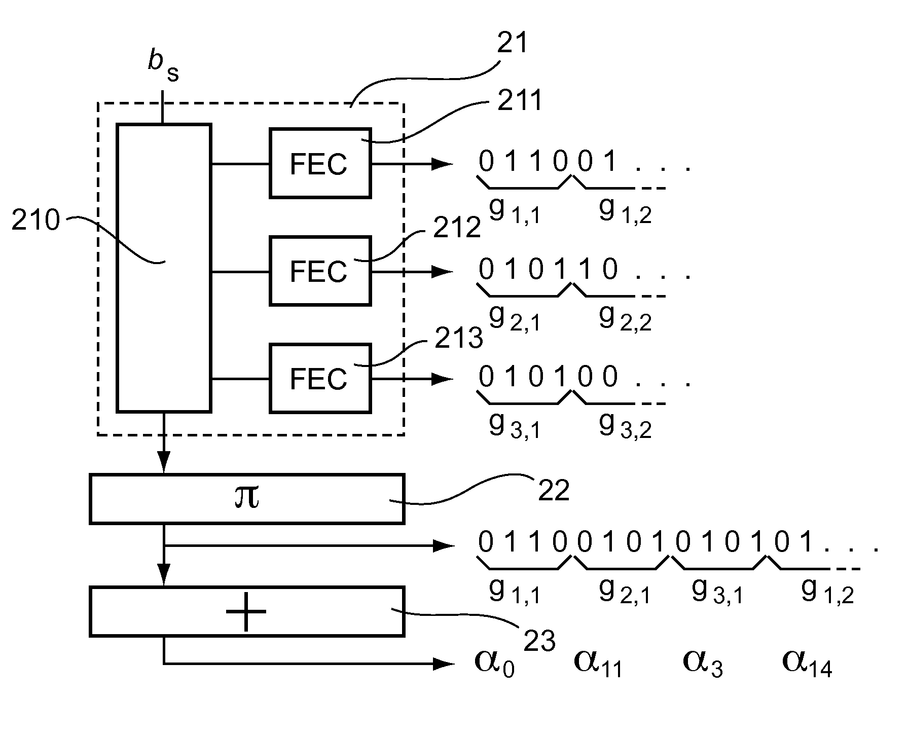
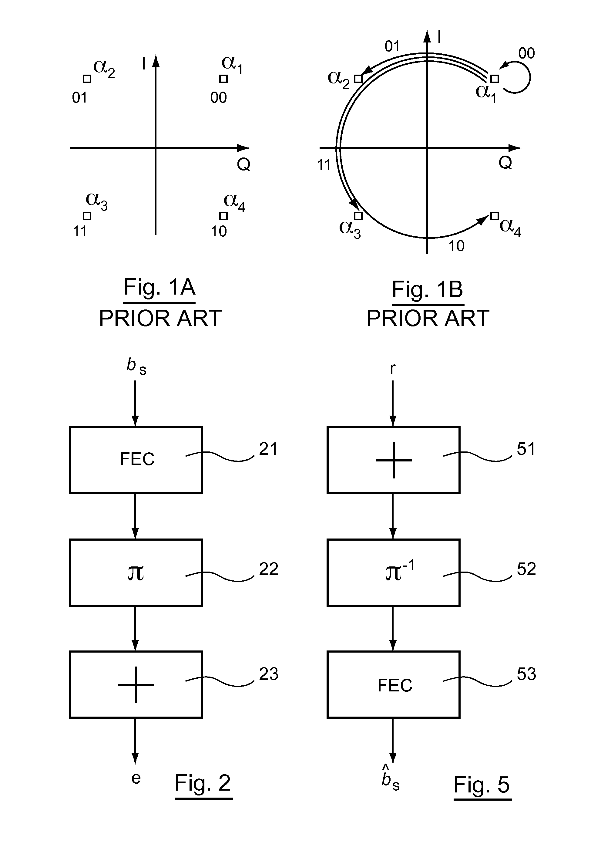
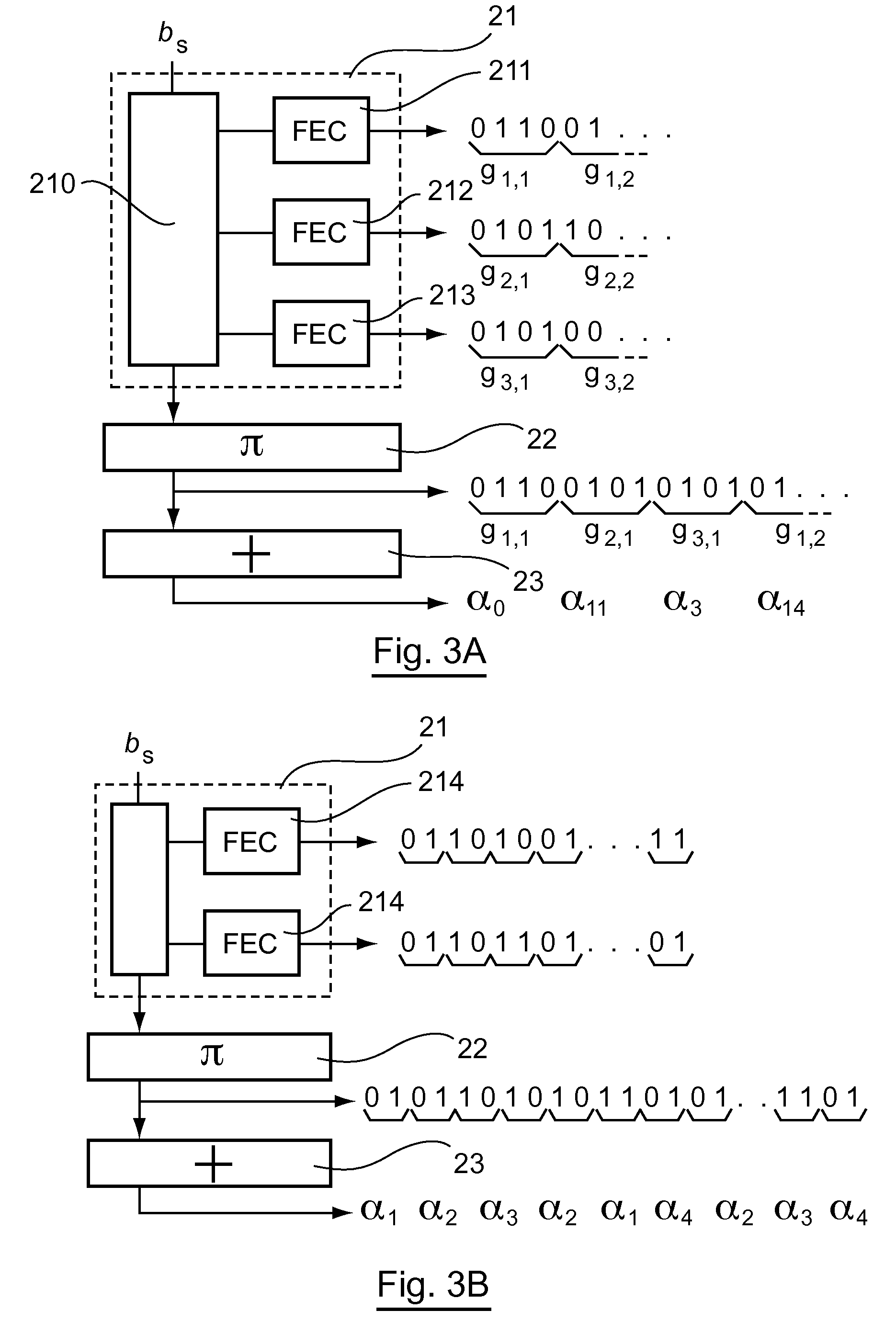
[0103]The general principle of an embodiment of the invention relies on a specific grouping of the bits forming a code word and a specific interlacing of these groups, enabling the distribution of the groups of the different code words in an interlaced sequence so that two adjacent groups (i.e. groups side by side in the interlaced sequence) belong to distinct code words. It can be noted that these adjacent groups correspond to consecutive transitions, corresponding for example to consecutive phase shifts between the modulated symbols for a phase modulation.

[0104]In other words, an embodiment of the invention proposes to distribute the errors occurring, during transmission, in the different code words. The code words coming from the error correction encoding are therefore interlaced so as not to have two groups of bits coming from a same code word side by side. If a transmission error occurs, it thus corrupts two groups of bits side by side that belong to d...


PUM


Abstract

A method and apparatus are provided for modulating a binary source sequence including of a plurality of source words to generate modulated symbols. The method implements error-correction encoding of the plurality of source words, implementing one or more encoding modules, each implementing a separate error-correction code to generate a plurality of code words, the source words being encoded in series. The code words are interlaced to generate an interlaced sequence. The interlaced sequence is differentially modulated to generate modulated symbols. Each code word is broken down into at least one group with a number of bits equal to the base-2 logarithm of a number of states of a modulation implemented by the step of differentially modulating. The interlacing step distributes the groups such that two adjacent groups in the interlaced sequence belong to separate code words.

Description

CROSS-REFERENCE TO RELATED APPLICATIONS[0001]This Application is a Section 371 National Stage Application of International Application No. PCT / EP2010 / 054467, filed Apr. 2, 2010 and published as WO 2010 / 112606 on Oct. 7, 2010, not in English.STATEMENT REGARDING FEDERALLY SPONSORED RESEARCH OR DEVELOPMENT[0002]None.THE NAMES OF PARTIES TO A JOINT RESEARCH AGREEMENT[0003]None.FIELD OF THE DISCLOSURE[0004]The field of the disclosure is that of digital communications.[0005]More specifically, the disclosure pertains to the transmission of data implementing a differential modulation type of modulation format. Such a differential modulation transforms a binary sequence into a modulated signal. The binary sequence at input of the modulation step corresponds to the transitions between the states of the constellation of the modulation used to generate the modulated symbols. A differential modulation can be seen as a differential encoding of a binary sequence, delivering another binary sequence...

Claims


Application Information

Patent Timeline
Patent Type & Authority Patents(United States)
IPC IPC(8): H03M13/00H04L1/00
CPCH04L1/0071H04L1/0047H04L1/0042H04L1/0054H04L1/0057H03M13/00H04L1/00H04L27/18
Inventor MUMTAZ, SAMIREKAYA-BEN OTHMAN, GHAYAJAOUEN, YVES
Owner INST MINES TELECOM
Learn More