Although very accurate and not intrinsically affected by the measurement errors caused by deformation due to the force of gravity acting on the bar, it is very slow and therefore unsuitable for being implemented on the
production line, where the cycle times are too short; in particular, the current
processing plants, for example in the
brass sector, process bundles at a speed of about 60-120 m / min, therefore producing finished bars of a length of 3 to 5 m at a frequency of one bar every 1-3 seconds.
However, the aforesaid technique requires much longer measurement times and is therefore only traditionally used to check samples next to the line.
However, these systems are designed to detect the
waviness of the material before it is
cut into bars and are, therefore, not often used, or even unused, once the production speed is increased, due to material deformations and oscillations caused by the speed and drive
system; moreover, these systems measure the material before it is
cut into bars and subjected to a longitudinal traction force, therefore neither considering the effect of the
cutting process on the finished product nor providing indications with regard to the effect of the
residual stress in the material, which can deform the bar following the
cutting process.
Other measurement systems, used to estimate the curvature of the material, use multiple contact sensors coupled to an apposite rolling surface, but are disadvantageously only
usable under well-controlled measuring conditions and difficult to adapt to the measurement of bars with sections that are not round; moreover, these systems often involve measurement errors caused by, for example, friction and unpredictable rolling of the material, mechanical adjustments or wearing of the components; therefore, also these systems are not very effective in carrying out dimensional checks on the
production line.
Moreover, these systems measure the magnitude of the straightness error of the material, but these measures are always indirect and unable to accurately provide the effective measure of the straightness error of the material.
Devices using optical sensors were also proposed, but these do not, however, provide satisfactory results in terms of the precision and accuracy of the measurement carried out; in particular, all of the currently known solutions proposed do not provide a compensation of the measurement errors intrinsically caused by the deformation of the bar generated by the force of gravity acting on the bar itself, errors which can progressively become very significant for materials that gradually become thinner and more flexible.
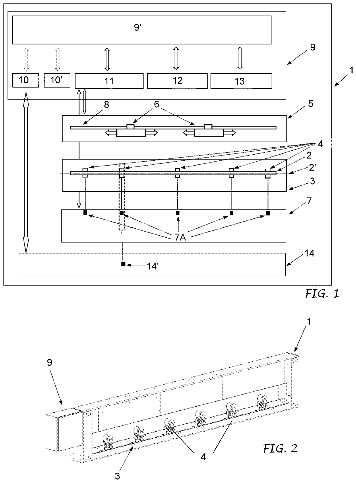
In any case, it is necessary to have a couple of sensors at each section of the bar to be measured, which requires the presence of a high number of measuring sensors, at least six sensors in a minimum configuration and without achieving a particularly accurate measurement.
Moreover, the presence of only two measures for each section does not allow to obtain a particularly accurate estimate of the real center position of the bar section analyzed; moreover, the determination of this center is only accurate in case of circular bodies, the measurement being essentially based on a shadow projection and not on the effective survey of the geometry of the section of the material.
Moreover, the system does not provide any compensation of the effects of gravity on the bar, and is therefore extremely inaccurate in case of slender bodies with geometries that can be easily deformed only by the force of their own weight.
In addition to presenting the same problems of the apparatus according to the document WO2006138228 A1, the fact that the tube is cantileverly restrained can cause further bending of the tube due to its weight.
Moreover, this system can measure straightness defects in only one direction and is completely unsuitable for being used on the
production line.
The system cannot therefore detect if the bar of reference is effectively devoid of straightness errors; moreover, such a system is not very flexible given the necessity to have the image of a corresponding bar of reference in order to be able to evaluate a bar.
However, these solutions still have practical use limitations and, more specifically, require an often not so easy configuration of the bar
supporting system on the basis of the length of the body to be measured; moreover being based on a thrust and counterthrust equilibrium system on the bar, therefore requiring rather long adjustment times before reaching the equilibrium required to carry out the measurement.
Therefore, these may not always be compatible with the cycle times available in the continuous cycle production plants.

