Operating method for a pivotal poly-plane imaging unit for imaging a moving examination object

a technology examination object, which is applied in the field of pivotal polyplane imaging unit for imaging a moving examination object, can solve the problems of limiting or even completely preventing clinical use of these representations, continually moving examination objects, and particularly clear problems, so as to achieve simple and efficient image generation and improve the reliability of image reconstruction

Inactive Publication Date: 2012-03-13
SIEMENS HEALTHCARE GMBH
View PDF12 Cites 2 Cited by
  • Summary
  • Abstract
  • Description
  • Claims
  • Application Information

AI Technical Summary

Benefits of technology

[0018]Therefore according to the invention outstanding representations of the examination object can be created in a very short time, it being possible to reduce the radiation dose and the quantity of contrast medium to be administered. Even more details, for example soft tissue in the vicinity of the characteristic structures, may also be depicted by the images recorded in one rotational pass. Furthermore, the inventive operating method is not dependent on the examination object moving periodically, instead any desired movements may be used. No ECG signal is required for a successful execution of the inventive operating method either.
[0020]Vessels (such as their outer contours), their center lines, or both, are preferably used as the characteristic structures. This allows particularly simple and efficient image generation, in particular if the examination object is the heart.
[0021]The reconstruction of the images can be made even more reliable if markers to calculate additional data points for determining the three-dimensional displacement vector fields are applied. This is particularly advantageous with reconstruction of the heart, it then being possible to apply the markers to the chest.

Problems solved by technology

In reality this is not always the case however as with many examination objects breathing, heartbeat or peristalsis, for example, cause movements in the examination object.
Such movements cause artifacts in the images produced which sometimes significantly restrict or even entirely prevent clinical use of these representations.
This problem occurs particularly clearly in the case of continually moving examination objects, such as the heart for example.
While an attempt can be made to remedy this problem by reducing the recording time of the raw data by way of quicker rotational movements of the CT device or by using two CT devices, this approach is not suitable for current C-arm devices.
However this requires long times for data acquisition, and this leads to problems in particular if contrast medium is used or if for example further movements have to be suppressed by holding one's breath.

Method used


Image

  • Operating method for a pivotal poly-plane imaging unit for imaging a moving examination object
  • Operating method for a pivotal poly-plane imaging unit for imaging a moving examination object
  • Operating method for a pivotal poly-plane imaging unit for imaging a moving examination object

Examples


Embodiment Construction

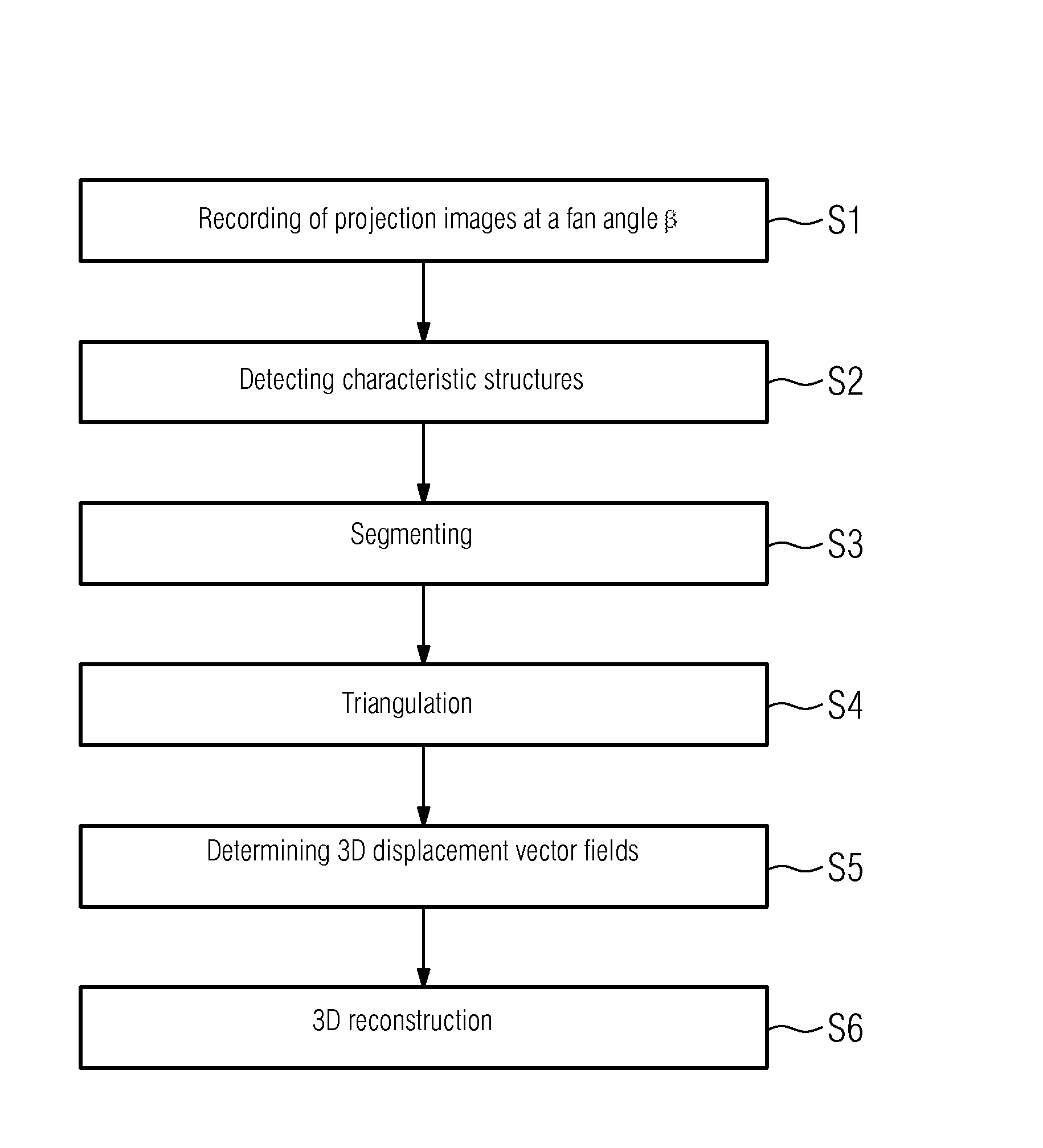
[0032]In its preferred embodiment for image recording the invention does not use a typically used mono-plane X-ray system, but a bi-plane C-arm X-ray system.

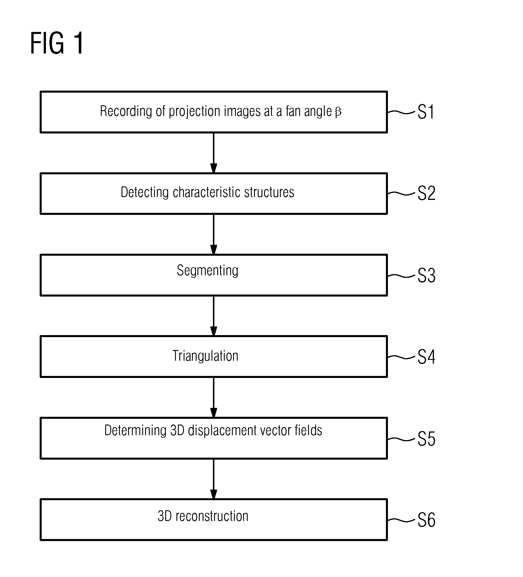
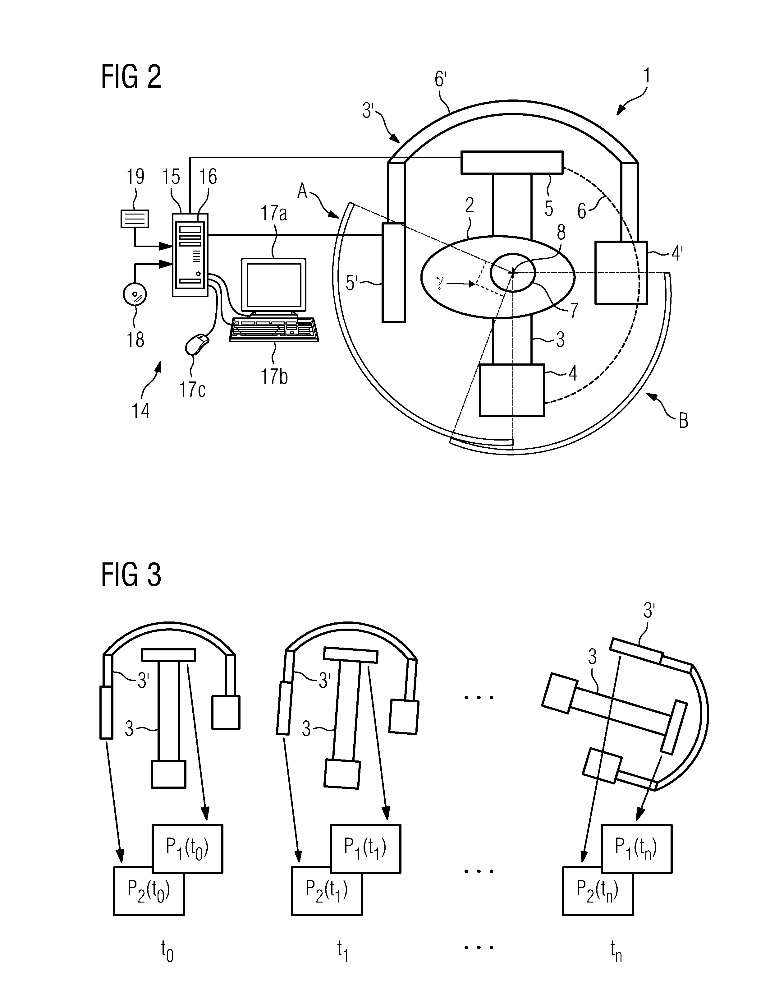
[0033]FIG. 2 schematically shows a device 1 for producing a three-dimensional image data record of an examination object. The device 1 is a bi-plane X-ray tomograph, in particular a bi-plane 3D rotational angiography device. The examination object is the chest region, in particular the heart 7, of a patient 2.

[0034]In a first imaging plane A the device 1 comprises a recording unit 3 having an X-ray radiator 4 and an X-ray detector 5. The X-ray radiator 4 and the X-ray detector 5 are attached to the ends of what is known as a C-arm 6 (shown only in broken lines) so as to oppose each other and together with the latter define the first imaging plane A. The C-arm 6 is in turn substantially centrally mounted on a stand (not shown) so as to rotate about an isocentric shaft 8. The X-ray radiator 4 and the X-ray detector 5 can be rotate...


PUM


Abstract

The invention relates to a pivotal poly-plane imaging unit having a first and a second imaging planes arranged relative to each other at an offset angle and recording projection images of an moving examination object at a fan angle β. First and second projection images are recorded in different relative positions at respective instants by pivoting the imaging planes at an angle at least 180°+β. Characteristic structures in the first and second projection images are detected. The characteristic structures are segmented by a vectorial representation and triangulated to obtain a three-dimensional representation of the characteristic structures. Three-dimensional displacement vector fields are determined that indicate displacements of the three-dimensional representation of the characteristic structures relative to a reference instant. A three-dimensional image is reconstructed using the three-dimensional displacement vector fields to display a state of the moving examination object at the reference instant.

Description

CROSS REFERENCE TO RELATED APPLICATIONS[0001]This application claims priority of German application No. 10 2008 026 035.5 filed May 30, 2008, which is incorporated by reference herein in its entirety.FIELD OF THE INVENTION[0002]The present invention relates to an operating method for a pivotal poly-plane imaging unit for imaging a moving examination object, in particular to a method for imaging the heart by means of an angiography device, for which purpose a bi-plane C-arm device shall be used by way of example here, and to a corresponding computer program, to a data carrier on which this is stored, and to a pivotal poly-plane imaging unit for carrying out the operating method.BACKGROUND OF THE INVENTION[0003]The term “poly-plane imaging unit” shall hereinafter be taken to mean an imaging unit comprising not just one pivotal plane, but a plurality of pivotal planes, in particular two or three, for image recording.[0004]This invention relates in particular to angiography systems as a...

Claims


Application Information

Patent Timeline
Patent Type & Authority Patents(United States)
IPC IPC(8): G06K9/00H05G1/64
CPCA61B6/032A61B6/4014A61B6/466A61B6/481A61B6/504G06T7/0065A61B6/4441G06T2207/10116G06T2207/30101G06T7/55
Inventor HEIGL, BENNO
Owner SIEMENS HEALTHCARE GMBH
Why Eureka
Try Eureka