Method for forming high-strength steel into a C-shape

a high-strength steel and c-shape technology, applied in the direction of metal-working feeding devices, manufacturing tools, positioning devices, etc., can solve the problems of inconvenient bending of hss sheet forming, adverse impact on hss sheet forming quality, and additional post-production

Inactive Publication Date: 2014-10-14
WUU SHIANG INDAL
View PDF3 Cites 5 Cited by
  • Summary
  • Abstract
  • Description
  • Claims
  • Application Information

AI Technical Summary

Benefits of technology

[0007]A primary object of the present invention is to provide a method for forming high-strength steel into a C-shape, which can avoid recoil after the HSS is formed.
[0008]Another object of the present invention is to provide a method for forming high-strength steel into a C-shape, which can shorten the forming process because of the avoidance of recoil.
[0009]Still another object of the present invention is to provide a method for forming high-strength steel into a C-shape, which can improve quality of finished products being formed by means of one-time forming.

Problems solved by technology

Thus, the quality of HSS sheet forming will be adversely affected.
Moreover, an additional post-production is required because the desired shape can not be accomplished at a time.
Any of the above processes is lengthy and tardy.
It is very uneconomic.
Furthermore, the forming process with multiple forming and trimming steps may also reduce lifetime of the dies.
It is disadvantageous to the latter process.

Method used


Image

  • Method for forming high-strength steel into a C-shape
  • Method for forming high-strength steel into a C-shape
  • Method for forming high-strength steel into a C-shape

Examples


Embodiment Construction

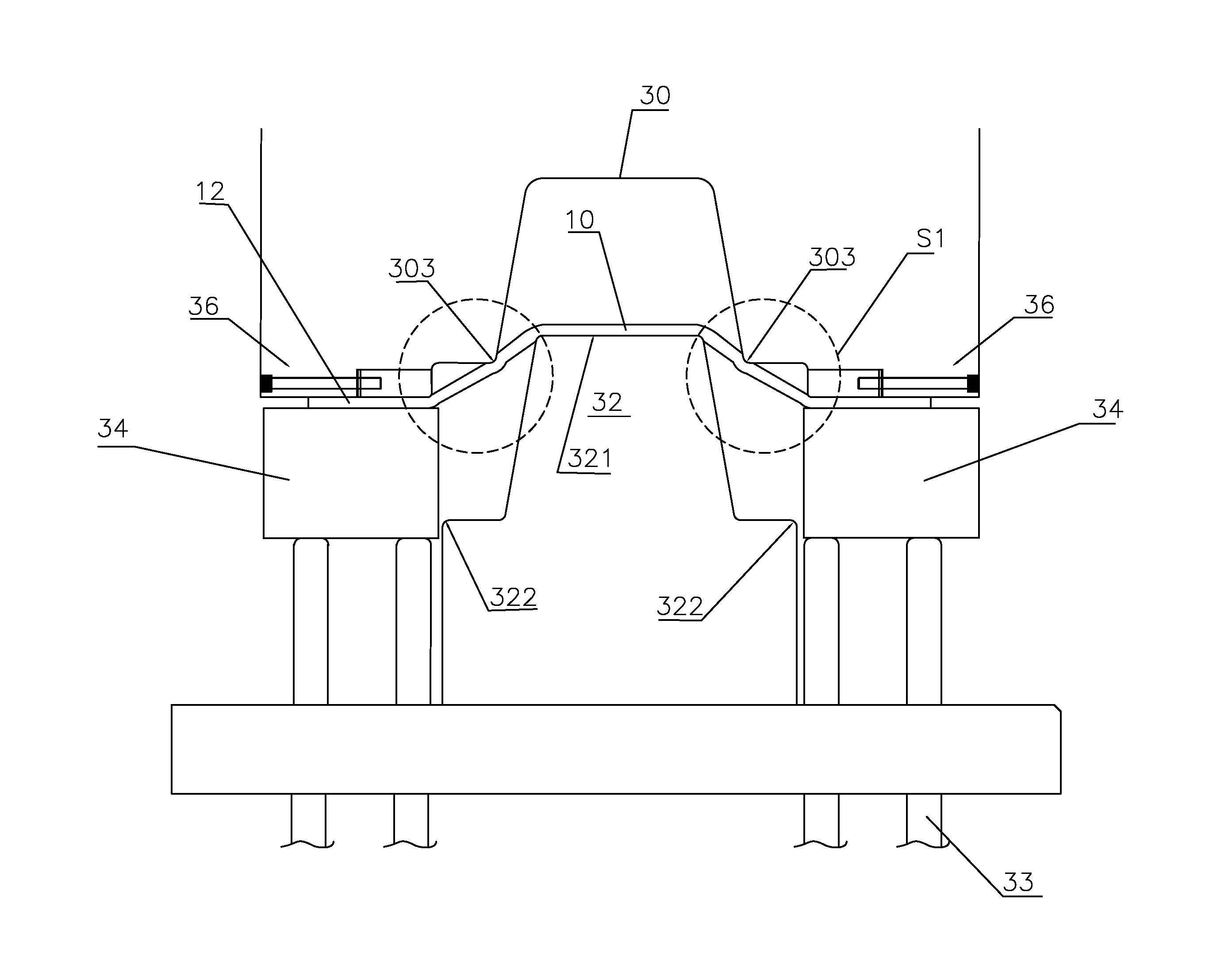
[0022]Referring to FIG. 3, the method of the invention is implemented by a power press machine includes a convex die 32, a concave die 30 and two depressors 34. The concave die 30 and the depressors 34 are moved by a first driving unit 31 and a second driving unit 33 to reciprocate upward and downward, respectively. The concave die 30 is formed with a concavity 301 and two recesses 302. And an angle 303 is formed by the concavity 301 and each the recess 302. The convex die 32 is composed of a protrusion 321 and two shoulders 322 respectively corresponding to the concavity 301 and the recesses 302 of the concave die 30 in shape and position. The depressors 34 are placed separately beside the convex die 32.

[0023]Initially, a high-strength steel (hereinafter “HSS”) 10 is placed on the protrusion 321 of the convex die 32 and under the concave die 30 as shown in FIG. 3. In more detail, the middle portion of the HSS 10 is supported by the protrusion 321 and two opposite side portions 12 o...


PUM

PropertyMeasurementUnit
strengthaaaaaaaaaa
flexibilityaaaaaaaaaa
tensile strengthaaaaaaaaaa

Abstract

The method is performed by a power press machine composed of a concave die, a convex die with two shoulders and two depressors separately beside the convex die, and includes the steps of: a) placing the high-strength steel (HSS) on the convex die and under the concave die; b) moving the depressors to have two opposite side portions of the HSS clamped between the concave die and the depressors; c) moving the convex die to press the HSS and keeping the side portions immovable; d) forming two steps adjacent to the side portions by the shoulders; and e) cutting off the steps with the side portions.

Description

CROSS-REFERENCE TO RELATED APPLICATIONS[0001]This application is a continuation-in-part of U.S. patent application Ser. No. 12 / 324,837, filed Nov. 27, 2008, now abandoned.BACKGROUND OF THE INVENTION1. Technical Field[0002]The invention relates to steel sheet forming processes, more particularly to a technique of bending high-strength steels.2. Related Art[0003]Because metals have good strength and flexibility, they are usually used as a structural element requiring strength. When a force applied on a unit area of metal exceeds its tensile strength, the metal will not split like ceramic materials, but will be deformed. That is to say, metals have a property of plasticity, i.e. plastic deformation. Usually, a power press machine is used for deforming a metal. There is a concave die and a convex die in a power press machine. By means of stroke, the metal material being placed between the two dies can be deformed as the shape formed by the dies.[0004]FIG. 1 illustrates a conventional te...

Claims


Application Information

Patent Timeline
Patent Type & Authority Patents(United States)
IPC IPC(8): B21D22/00B21D22/02B21D22/06B21D22/22B21D24/04
CPCB21D22/02B21D22/06B21D22/22B21D24/04
Inventor CHIEN, YONG-WAH
Owner WUU SHIANG INDAL
Why Eureka
Try Eureka