Device for regulating the linear stability of a belt

a technology of linear stability and revolving belt, which is applied in the direction of rollers, conveyor parts, thin material handling, etc., can solve the problems of limited influence on the belt run, and inability to control the belt further, so as to ensure the linear stability of the belt, minimize the swinging movement of the belt, and ensure the effect of linear stability

Inactive Publication Date: 2014-10-21
ROBERT BOSCH GMBH
View PDF17 Cites 0 Cited by
  • Summary
  • Abstract
  • Description
  • Claims
  • Application Information

AI Technical Summary

Benefits of technology

[0006]The object on which the invention is based is to provide a device which ensures the linear stability of a belt in a transport installation, in particular in a discharge station, and which does not have the abovementioned disadvantages. In particular, instead of control between limit values, regulation around a desired value should be possible, in order thereby to minimize the swinging movement of the belt. The looping of the belt around the control roller should be as high as possible in order to ensure as strong an influence upon the belt run as possible. Control should take place from the belt inside which usually has higher and, above all, uniform friction, since this inside is not subjected to contamination by transported products.
[0007]Also, a simple change of the belt should be possible, without the latter having to be cut open and the new belt welded to the installation.

Problems solved by technology

The belt control known from EP-A-0 659 663 has the disadvantage that the control roller has only a low loop-around.
Only limited influence upon the belt run is therefore possible.
Moreover, the control roller acts upon the belt outside which, with progressive contamination, mostly allows ever lower friction or force transmission, and therefore the controllability of the belt is further impaired.
A further disadvantage arises in that the belt rollers are connected fixedly to the frame of the station.

Method used


Image

  • Device for regulating the linear stability of a belt
  • Device for regulating the linear stability of a belt
  • Device for regulating the linear stability of a belt

Examples


Embodiment Construction

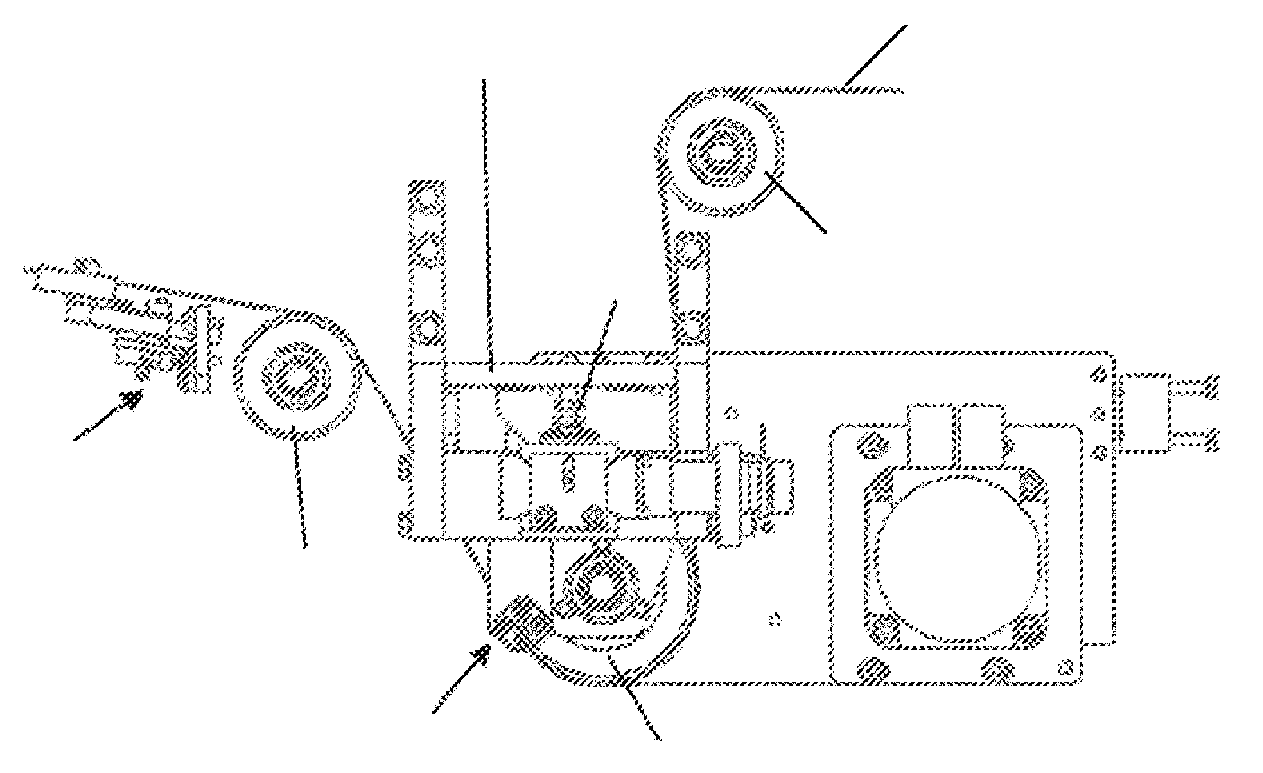
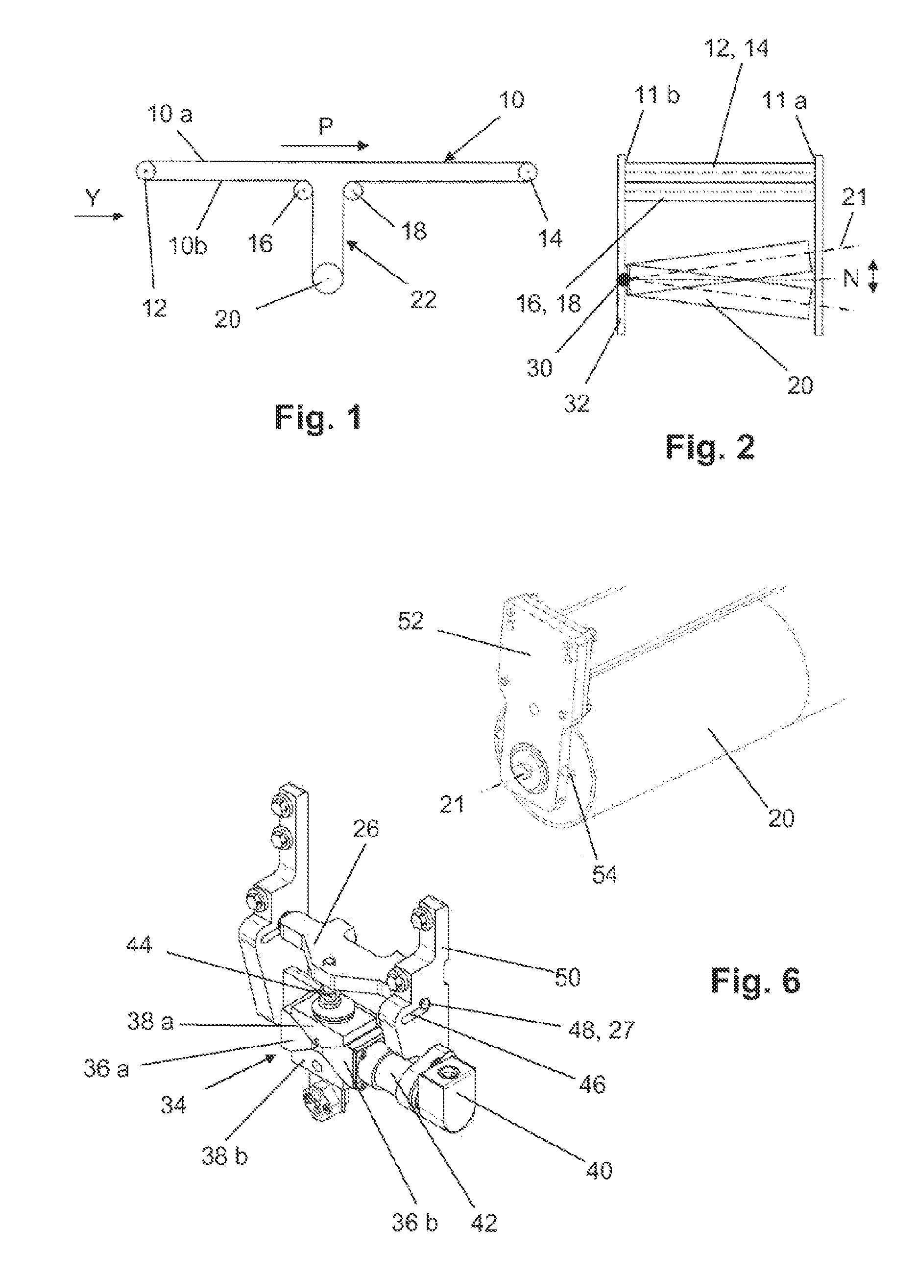
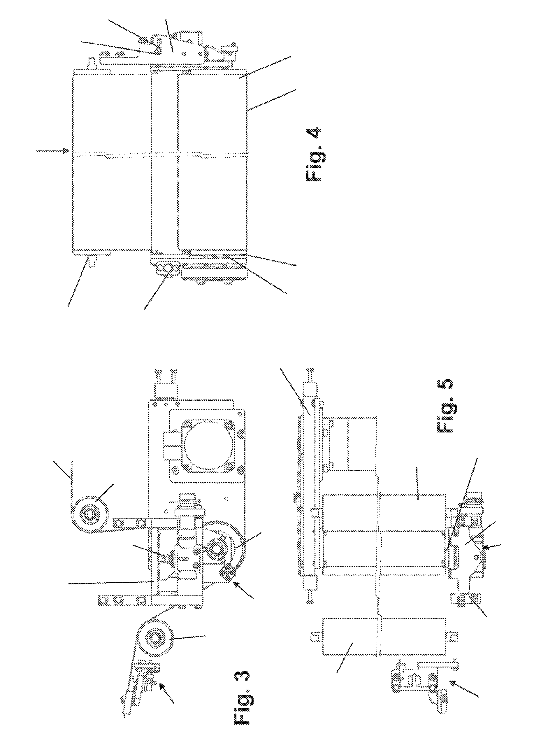
[0021]FIG. 1 shows an endless transport belt 10 with a horizontally running transport strand 10A and return strand 10B which are arranged between a first and a second deflecting roller 12, 14. The return strand 10B is shaped via a third and a fourth deflecting roller 16, 18 into a belt loop 22 projecting essentially perpendicularly from the horizontal plane of the transport strand 10A and looping around a drive and control roller 20. The belt 10 runs as a transport strand 10A in the direction of the arrow P. The belt 10 is, for example, 1.5 m wide and has two belt edges 11 running parallel to one another. In order to regulate the linear stability of the belt 10, the axle 21 of the drive and control roller 20 can be pivoted up and down about its normal horizontal location N. For this purpose, the drive and control roller 20 is articulated at one end on a machine frame 32 via a pivot bearing 30. The other end can be raised and lowered via a lifting mechanism described in more detail f...


PUM


Abstract

In a device for regulating the linear stability of a revolving belt (10) of a conveying system, a control roller (20) disposed transversely with respect to a belt running direction is pressed against the belt. The control roller (20) can be displaced by means of an actuator co-operating with a sensor detecting the lateral position of the belt (10) in order to displace the control roller (20) to align the belt if the belt (10) drifts laterally. The control roller (20) is mounted on an axle (21) which in the region of a first edge of the belt is pivotably mounted and in the region of a second edge of the belt is connected and movably guided at the second end thereof using guiding and adjusting means. The control roller (20) is disposed with a high degree of looping on the inner face of the belt in a belt loop (22) located substantially perpendicular to a conveying plane and can be pivoted substantially perpendicularly to the conveying plane.

Description

TECHNICAL FIELD[0001]The present invention relates to a device for regulating the linear stability of a revolving belt of a transport installation by means of a control roller which is arranged transversely to a belt running direction and is pressed against the belt and which can be deflected by means of an actuating drive cooperating with a sensor detecting the lateral position of the belt, in order, in the event of a lateral drift of the belt, to deflect the control roller for the purpose of aligning the belt, the control roller being mounted on an axle which is mounted pivotably in the region of a first edge of the belt and which is connected and displaceably guided at its second end in the region of the second edge of the belt by guidance and adjustment means.BACKGROUND OF THE INVENTION[0002]Transport installations with revolving belts are used, for example, as what are known as “discharge stations” and are described inter alia in U.S. Pat. No. 3,429,416 and EP-A-558 123. The pu...

Claims


Application Information

Patent Timeline
Patent Type & Authority Patents(United States)
IPC IPC(8): B65G15/60B65H23/00B65G39/16
CPCB65G39/16B65G15/60
Inventor MAIWALD, ANDREAS
Owner ROBERT BOSCH GMBH
Why Eureka
Try Eureka