
Tubular back beam for vehicle

a back beam and vehicle technology, applied in the direction of roofs, bumpers, vehicular safety arrangments, etc., can solve the problems of increasing damage to the vehicle body, ineffective adjustment of the back beam, and inability to effectively cope with offset crash, so as to increase the connection rigidity

Active Publication Date: 2014-10-21
HYUNDAI MOTOR CO LTD +1
View PDF7 Cites 6 Cited by
  • Summary
  • Abstract
  • Description
  • Claims
  • Application Information

AI Technical Summary

Benefits of technology

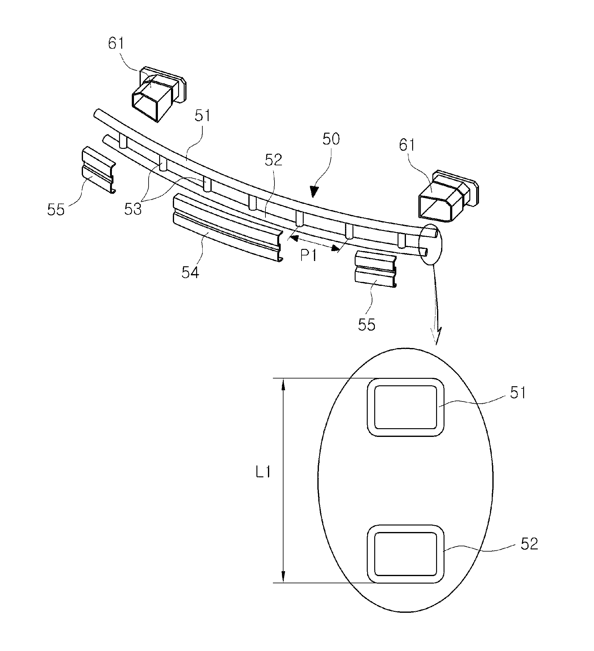
[0012]Various aspects of the present invention provide for a tubular back beam for a vehicle, intended to increase connecting rigidity between upper and lower beams, thus preventing the upper and lower beams from being separated from each other by crash energy, and more effectively satisfying crashworthiness in particular for a head-on crash and an offset crash.
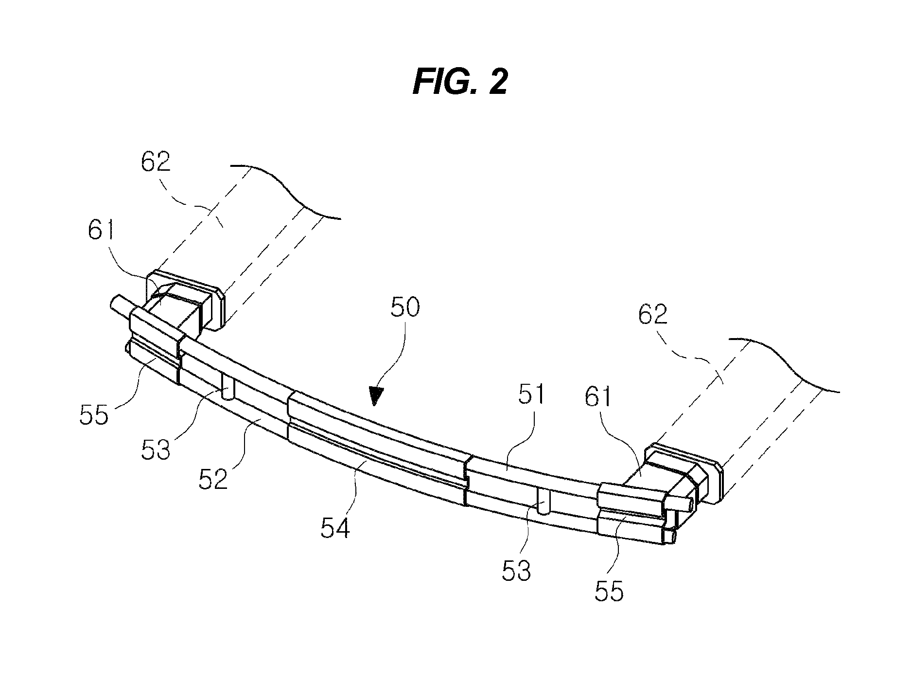
[0021]The tubular back beam for the vehicle according to the present invention is advantageous in that it can effectively cope with crashes including a head-on crash and an offset crash, etc., thus promoting excellent crashworthiness, and thereby maximally reducing damage to the vehicle body, and maximally mitigating injuries to a pedestrian and a passenger.

Problems solved by technology

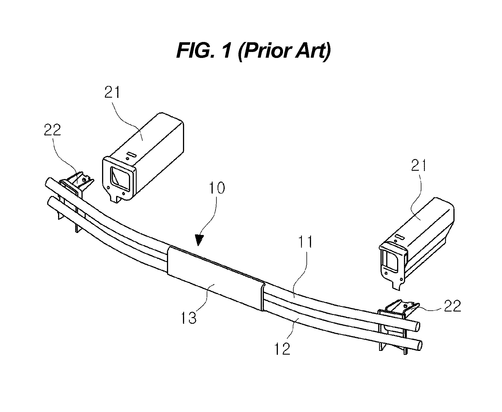
However, the conventional tubular back beam 10 is problematic in that the upper and lower beams 11 and 12 are connected to each other using only one connecting bracket 13, so that the rigidity of the connection between the upper and lower beams 11 and 12 is low, and thus the crash energy separates the upper and lower beams 11 and 12 from each other, in which case it is impossible to effectively cope with a crash, thus increasing damage to a vehicle body and injury to occupants of the vehicle.
Further, the conventional tubular back beam 10 is problematic in that the connecting bracket13 connecting the upper and lower beams 11 and 12 copes with a head-on crash, but there is no structure connecting the upper and lower beams 11 and 12 in the event of an offset crash of 40% or more, so that the back beam does not effectively cope with the offset crash.

Method used


Image

  • Tubular back beam for vehicle
  • Tubular back beam for vehicle
  • Tubular back beam for vehicle

Examples


Embodiment Construction

[0028]Reference will now be made in detail to various embodiments of the present invention(s), examples of which are illustrated in the accompanying drawings and described below. While the invention(s) will be described in conjunction with exemplary embodiments, it will be understood that present description is not intended to limit the invention(s) to those exemplary embodiments. On the contrary, the invention(s) is / are intended to cover not only the exemplary embodiments, but also various alternatives, modifications, equivalents and other embodiments, which may be included within the spirit and scope of the invention as defined by the appended claims.

[0029]As shown in FIGS. 2 and 3, the tubular back beam 50 for the vehicle in accordance with various embodiments of the present invention includes upper and lower beams 51 and 52, a plurality of connecting lugs 53, a center bracket 54, and a pair of side brackets 55. The upper and lower beams 51 and 52 each have a tubular structure an...


PUM


Abstract

A tubular back beam for a vehicle is provided to effectively cope with crashes, including a head-on crash, an offset crash, etc., thus promoting excellent crashworthiness, and thereby maximally reducing damage to a vehicle body, in addition to maximally mitigating injuries to a pedestrian and a passenger.

Description

CROSS-REFERENCE TO RELATED APPLICATIONS[0001]The present application claims priority of Korean Patent Application Number 10-2011-0133136 filed Dec. 12, 2011, the entire contents of which application is incorporated herein for all purposes by this reference.BACKGROUND OF INVENTION[0002]1. Field of Invention[0003]The present invention relates generally to a tubular back beam for a vehicle and, more particularly, to a tubular back beam for a vehicle, which is manufactured in the form of a tube to satisfy crashworthiness.[0004]2. Description of Related Art[0005]As a measure to protect a passenger as well as a vehicle body against a crash, back beams are mounted to the front and rear of the vehicle.[0006]FIG. 1 illustrates an example of a tubular back beam. A conventional tubular back beam 10 is configured so that upper and lower beams 11 and 12 each having a circular cross-section are spaced apart from each other in a vertical direction, and central portions of the upper and lower beams...

Claims


Application Information

Patent Timeline
Patent Type & Authority Patents(United States)
IPC IPC(8): B60R19/12
CPCB60R19/12B60R19/18B60R19/02
Inventor KIM, HYUN, GYUNG
Owner HYUNDAI MOTOR CO LTD
Learn More