
Two-level LED security light with motion sensor

a technology of led security lights and motion sensors, applied in the field of lighting equipment, can solve the problems of high fabrication cost and complex technology of led driver design and construction, and achieve the effect of saving energy

Active Publication Date: 2014-10-21
VAXCEL INT
View PDF2 Cites 52 Cited by
  • Summary
  • Abstract
  • Description
  • Claims
  • Application Information

AI Technical Summary

Benefits of technology

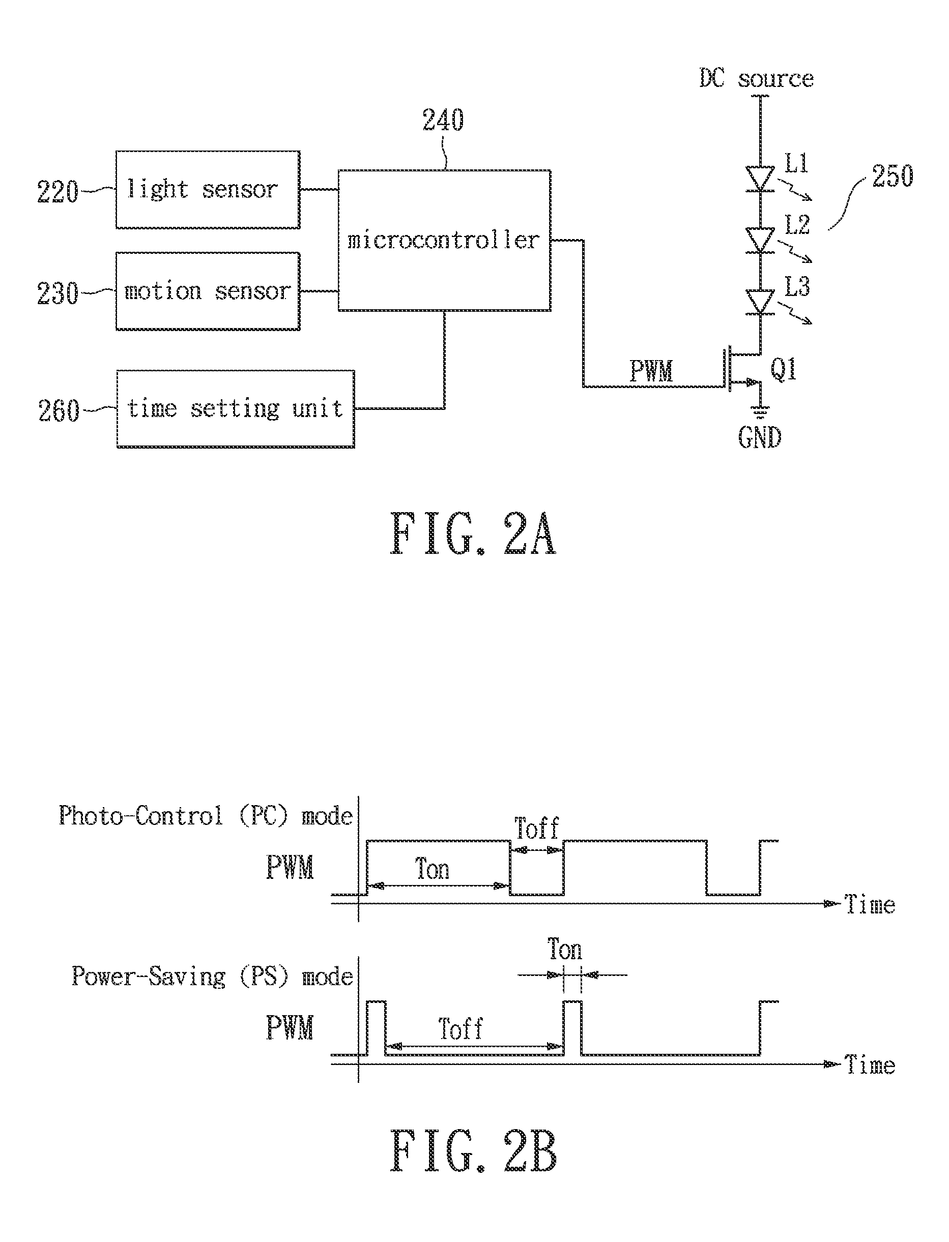
[0006]An exemplary embodiment of the present disclosure provides a two-level LED security light with motion sensor which may switch to high level illumination in the Power-Saving (PS) mode for a predetermined duration time when a human motion is detected thereby achieve warning purpose using method of electric current or lighting load adjustment. Furthermore, prior to the detection of an intrusion, the LED security light may be constantly in the low level illumination to save energy.
[0012]To sum up, a two-level LED security light with motion sensor provided by an exemplary embodiment in the preset disclosure, may execute Photo-Control (PC) and Power-Saving (PS) modes. When operates in the PC mode, the lighting apparatus may auto-illuminate at night and auto turn off at dawn. The PC mode may generate a high level illumination for a predetermined duration then automatically switch to the PS mode by a control unit to generate a low level illumination. When the motion sensor detects a human motion, the disclosed LED security light may immediate switch to the high level illumination for a short predetermined duration thereby achieve illumination or warning effect. After the short predetermined duration, the LED security light may automatically return to the low level illumination for saving energy.

Problems solved by technology

In particular, the design and construction of LED drivers are still of a complex technology with high fabrication cost.

Method used


Image

  • Two-level LED security light with motion sensor
  • Two-level LED security light with motion sensor
  • Two-level LED security light with motion sensor

Examples


first exemplary embodiment

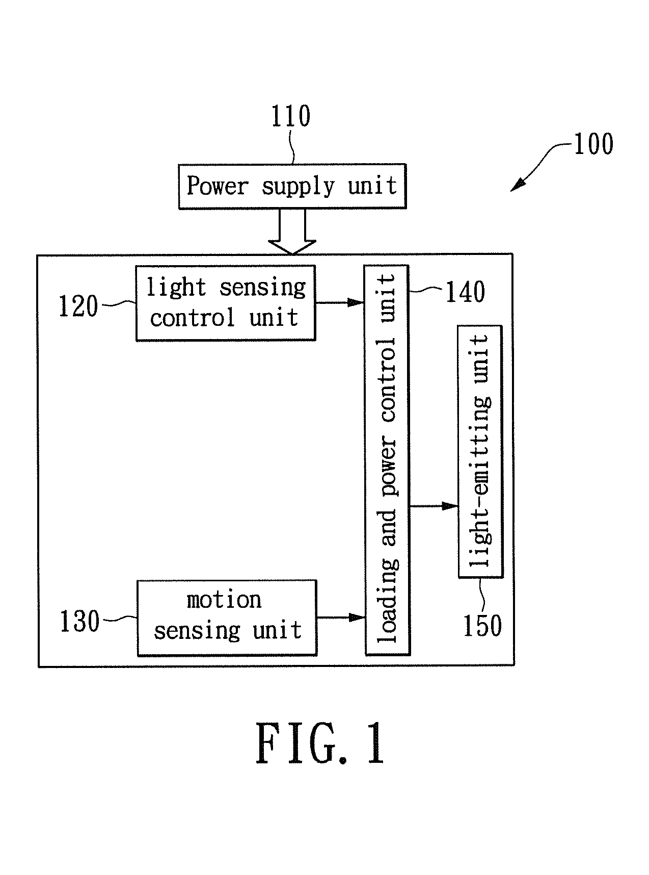
[0026]Refer to FIG. 1, which schematically illustrates a block diagram of a two-level LED security light in accordance to the first exemplary embodiment of the present disclosure. A two-level LED security light (herein as the lighting apparatus) 100 includes a power supply unit 110, a light sensing control unit 120, a motion sensing unit 130, a loading and power control unit 140, and a light-emitting unit 150. The power supply unit 110 is used for supplying power required to operate the system, wherein the associated structure includes the known AC / DC voltage converter. The light sensing control unit 120 may be a photoresistor, which may be coupled to the loading and power control unit 140 for determining daytime or nighttime in accordance to the ambient light. The motion sensing unit 130 may be a passive infrared sensor (PIR), which is coupled to the loading and power control unit 140 and is used to detect intrusions. When a person is entering a predetermined detection zone of the ...

second exemplary embodiment

[0033]Refer again to FIG. 1, wherein the illumination variations of the light-emitting unit 150 may be implemented through the number of light-source loads being turned on to generate more than two levels of illumination. The lighting apparatus 100 in the instant exemplary embodiment may be through turning on a portion of LEDs or all the LEDs to generate a low and a high level of illuminations.

[0034]Refer to FIG. 3A concurrently, which illustrates a schematic diagram of a two-level LED security light 100 in accordance to the second exemplary embodiment of the present disclosure. The main difference between FIG. 3A and FIG. 2A is in the light-emitting unit 350, having three series-connected LEDs L1˜L3 and NMOS transistors Q1 and Q2. The LEDs L1˜L3 are series connected to the transistor Q1 at same time connected between the DC source and a constant electric current control circuit 310. Moreover, transistor Q2 is parallel connected to the two ends associated with LEDs L2 and L3. The ga...

third exemplary embodiment

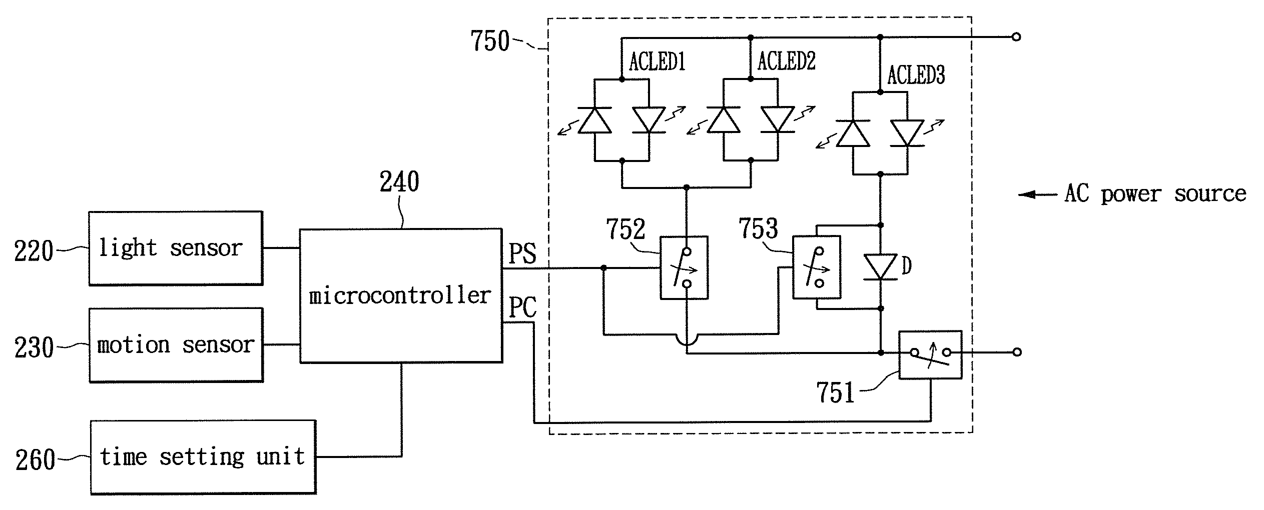
[0040]Refer back to FIG. 1, wherein the light-emitting unit 150 may include a phase controller and one or more parallel-connected alternating current (AC) LEDs. The phase controller is coupled between the described one or more parallel-connected ACLEDs and AC power source. The loading and power controller 140 in the instant exemplary embodiment may through the phase controller adjust the average power of the light-emitting unit 150 so as to generate variations in the low level and the high level illuminations.

[0041]Refer to FIG. 4A, which illustrates a schematic diagram of a two-level LED security light 100 in accordance to the third exemplary embodiment of the present disclosure. The main difference between FIG. 4A and FIG. 3 is in that the light-source load is an ACLED, which is coupled to the AC power source, and further the light-emitting unit 450 includes a phase controller 451. The phase controller 451 includes a bi-directional switching device 452, here, a triac, a zero-cross...


PUM


Abstract

A two-level LED security light with a motion sensor. At night, the LED is turned on for a low level illumination. When the motion sensor detects any intrusion, the LED is switched from the low level illumination to a high level illumination for a short duration time. After the short duration time, the LED security light returns to the low level illumination for saving energy. The LED security light includes a power supply unit, a light sensing control unit, a motion sensing unit, a loading and power control unit, and a lighting-emitting unit. The lighting-emitting unit includes one or a plurality of LEDs which may be turned-on or turned-off according to the sensing results from the light sensing control unit. When the motion sensing unit detects an intrusion, the illumination of the LED security light can be immediately turned on to the high level to scare away the intruder.

Description

BACKGROUND[0001]1. Technical Field[0002]The present disclosure relates to a lighting apparatus, in particular, to a two-level security LED light with motion sensor[0003]2. Description of Related Art[0004]Lighting sources such as the fluorescent lamps, the incandescent lamps, the halogen lamps, and the light-emitting diodes (LED) are commonly found in lighting apparatuses for illumination purpose. Photoresistors are often utilized in outdoor lighting applications for automatic illuminations, known as the Photo-Control (PC) mode. Timers may be used in the PC mode for turning off the illumination or for switching to a lower level illumination of a lighting source after the lighting source having delivered a high level illumination for a predetermined duration, referred as the Power-Saving (PS) mode. Motion sensors are often used in the lighting apparatus for delivering full-power illumination thereof for a short duration when a human motion is detected, then switching back to the PS mo...

Claims


Application Information

Patent Timeline
Patent Type & Authority Patents(United States)
IPC IPC(8): H05B33/08G08B13/189H05B37/02G08B15/00H05B44/00
CPCG08B13/189Y02B20/40H05B33/0827Y02B20/44Y02B20/46H05B33/0872H05B37/0218G08B15/00H05B37/0227H05B39/044H05B33/0815H05B33/0854H05B45/20H05B45/46H05B47/11Y02B10/10H05B47/115H05B47/17H05B45/12H05B45/14H05B45/44H05B45/48H05B47/16H05B45/37H05B47/10H05B45/10H05B47/105H05B39/042F21Y2115/10F21S9/03F21V17/02G08B5/36G08B13/1895G08B15/002G08B13/00H02J7/35
Inventor CHEN, CHIA-TEH
Owner VAXCEL INT
Learn More