Antenna with integrated RF module

a radio frequency module and antenna technology, applied in the direction of antennas, antenna details, protective materials, etc., can solve the problems of internal antennas not meeting the performance of external antennas, limited antenna placement within enclosures, transmission and/or reception, etc., to achieve the effect of minimizing signal loss

Active Publication Date: 2014-10-21
TEXAS LFP
View PDF17 Cites 4 Cited by
  • Summary
  • Abstract
  • Description
  • Claims
  • Application Information

AI Technical Summary

Benefits of technology

[0005]According to one aspect of the invention, an antenna assembly includes an antenna housing, an antenna located within the housing, a radio frequency module located within the housing, and at least one electrical conductor operably associated with the module. The module includes a radio frequency device selected from the group of transmitters, receivers and transmitters. The device is electrically connected to the antenna. The at least one electrical conductor may provide external power to the module or conduct processed signals between the module and external circuitry without significant signal loss.
[0006]According to a further aspect of the invention, a wireless device comprises a compartment, first electronic circuitry located within the compartment and an antenna assembly connected to the compartment. The antenna assembly includes an antenna housing, an antenna located within the housing, second electronic circuitry including a radio frequency module located within the housing and electrically connected to the antenna for transmitting and / or receiving radio signals, and a cable assembly extending between the first and second electronic circuitry. The cable assembly has first and second wires connectable to a power supply associated with the first electronic circuitry and at least a third wire connected between the first and second electronic circuitry to conduct processed signals therebetween without significant signal loss.
[0007]According to an even further aspect of the invention, an antenna assembly comprises an antenna housing, an elongate antenna located within the housing, and a radio frequency (RF) module located within the housing. The RF module includes an elongate printed circuit board (PCB), a distal end of which is electrically connected to a proximal end of the antenna, and a radio frequency device located on the PCB proximal to the antenna and electrically connected thereto to thereby minimize signal loss therebetween. An elongate conductive sleeve is also located in the housing and surrounds the PCB. A proximal end of the conductive sleeve is electrically connected to a proximal end of the PCB to thereby provide a ground plane for the antenna. A cable assembly has a distal end connected to the proximal end of the PCB and a proximal end for connection to external circuitry. The cable assembly may be in the form of one or more electrical wires or other electrically conductive material for a) providing external power to the module and / or b) conducting processed signals between the module and external circuitry without significant signal loss.

Problems solved by technology

Consumer demand for more compact wireless products has caused many manufacturers to move the antenna to the inside of the product's enclosure, but not without compromise.
Also, the location of the antenna within the enclosure is limited since the user's hand may cover the antenna and therefore limit transmission and / or reception.
In many cases, the internally mounted antenna cannot match the performance of an externally mounted antenna.
However, these devices still suffer from the hand effect and cannot work inside metal enclosures.
This cable has a loss associated with it that reduces the amount of energy transmitted between the antenna and the RF module.
In addition, the cost of the cable, RF connectors and labor associated with assembling the external antenna can be prohibitive in many applications.
Although there are antennas that directly mount to the RF modules, these types of devices require the use specialized connectors which again produce loss and are expensive.

Method used


Image

  • Antenna with integrated RF module
  • Antenna with integrated RF module
  • Antenna with integrated RF module

Examples


Embodiment Construction

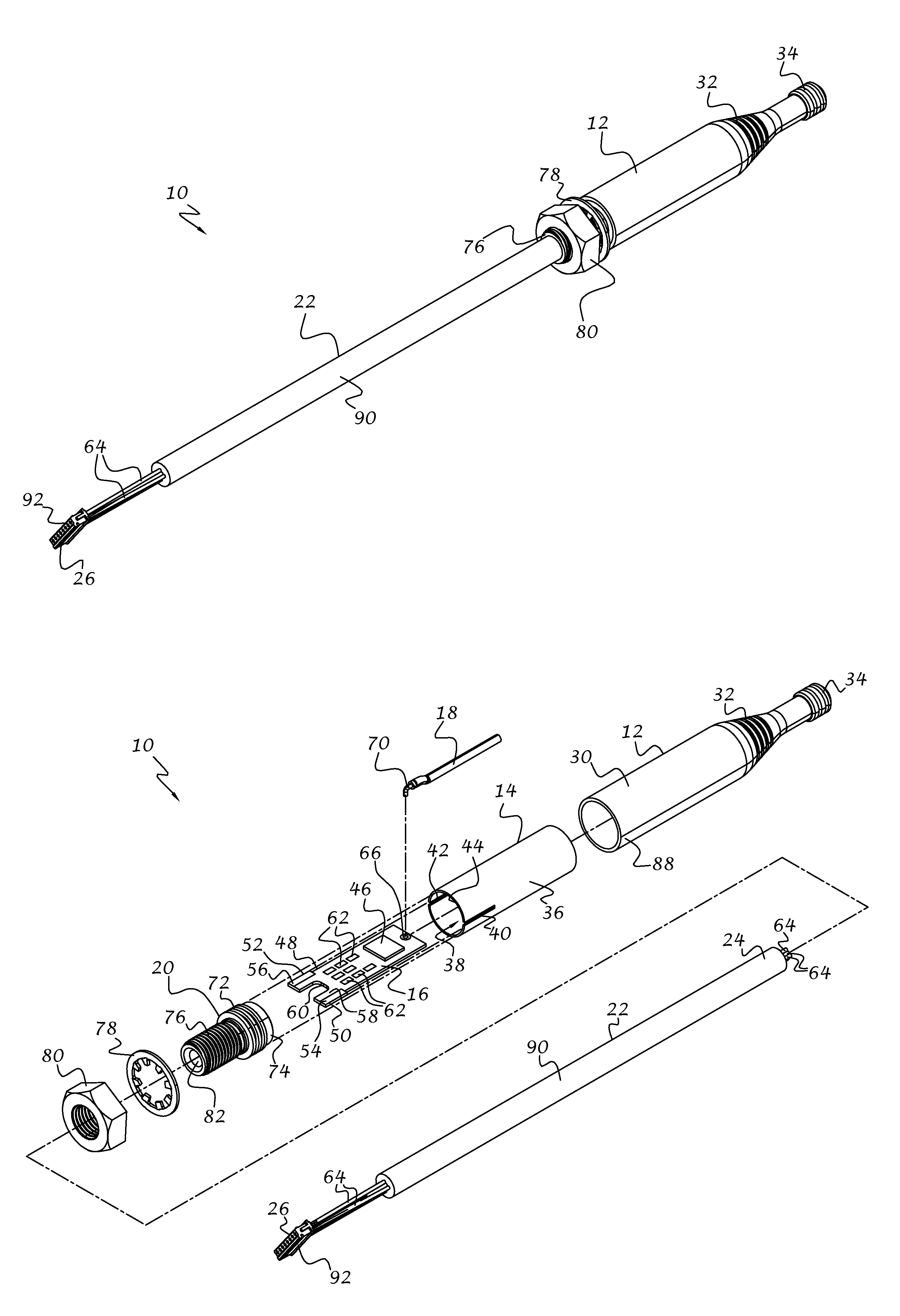
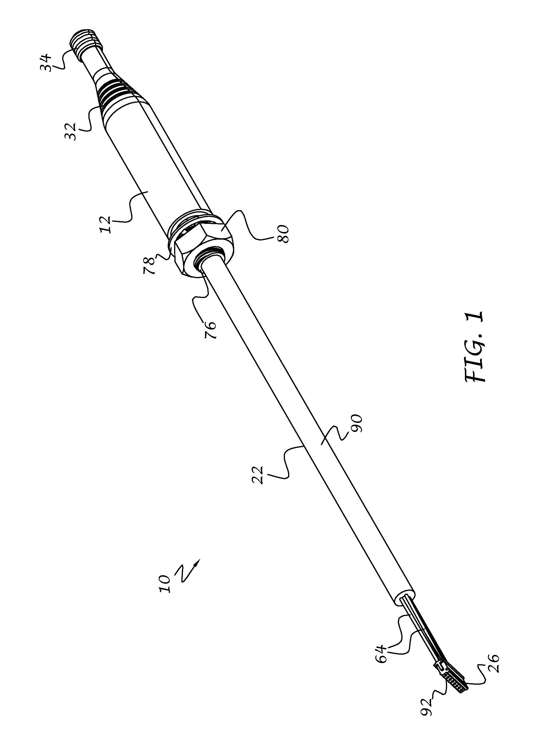
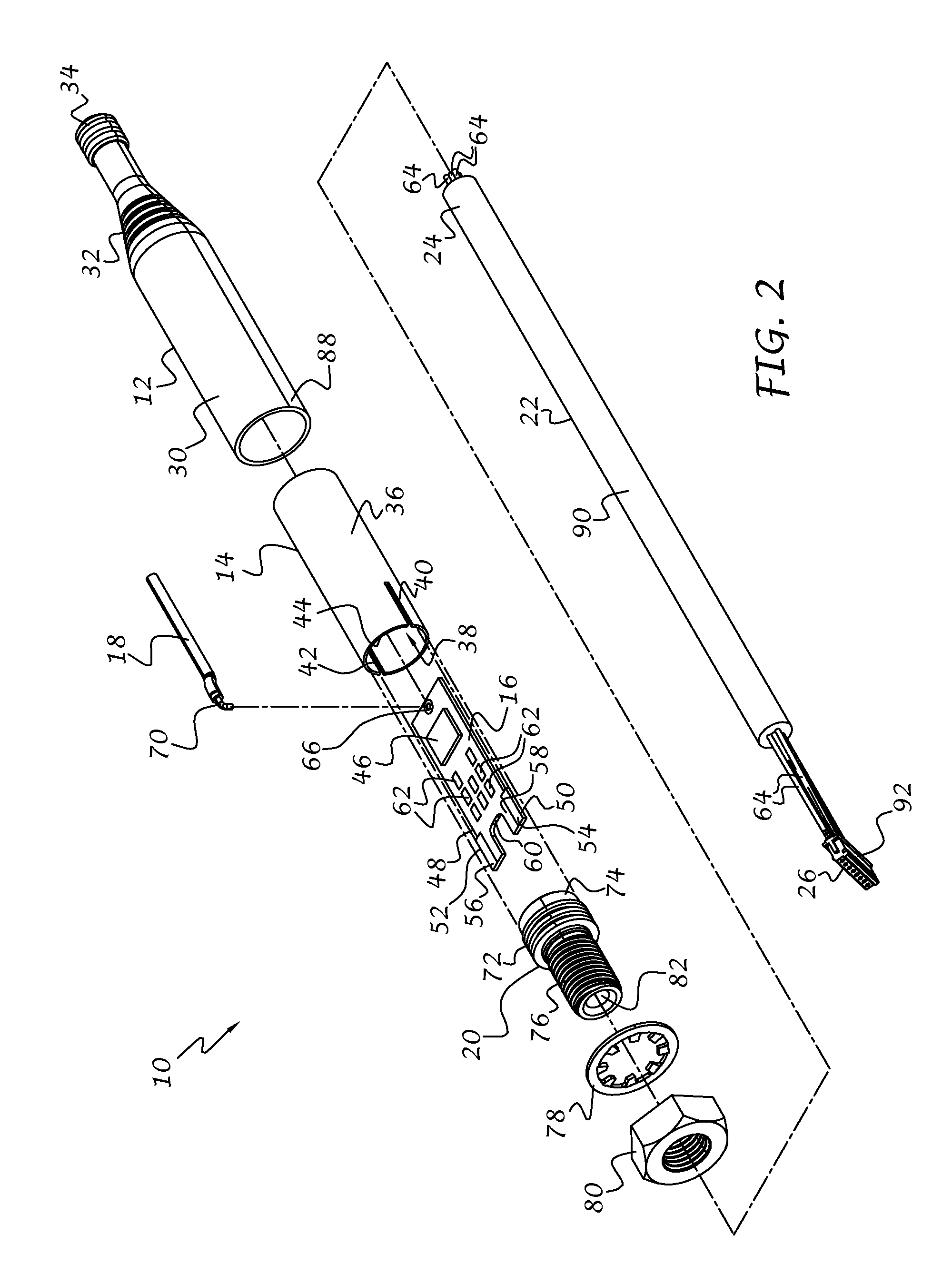
[0023]Referring now to the drawings, and to FIGS. 1-5 in particular, an antenna assembly 10 in accordance with the present invention is illustrated. The antenna assembly 10 can be adapted for use with any type of wireless device where the transmission and / or reception of signals is desired, including but not limited to: mobile phones, personal computers, wireless networks, gaming devices, wireless sensors, radios, walkie-talkies, transponders, and so on.

[0024]The antenna assembly 10 preferably includes an antenna housing 12, a sleeve 14 located within the housing, a radio frequency (RF) module 16 located within the sleeve 14, and an antenna 18 extending forwardly from the module 16. A mounting base 20 extends into the housing 12 and sleeve 14. A wire assembly 22 extends through the base 20 and includes a distal end 24 that electrically connects to the module 16 and a proximal end 26 for connection to exterior circuitry 28 (FIG. 5). A volume 25 of potting material is positioned withi...


PUM


Abstract

An antenna assembly includes an antenna housing, an antenna located within the housing, a radio frequency (RF) module located within the housing and connected to the antenna, and a cable assembly operably associated with the module. The module includes a radio frequency device, such as a transmitter, receiver or transceiver, electrically connected to the antenna. The cable assembly includes electrical wires for providing external power to the module and conducting processed signals between the module and external circuitry. The proximal nature of the antenna and RF module reduces or eliminates induced power losses between the antenna and module, resulting in a very effective power transfer ratio. Resulting processed signals between external and internal processing circuitry can be conducted over relatively long lengths without appreciable signal loss.

Description

BACKGROUND OF THE INVENTION[0001]This invention relates generally to antennas, and more particularly to an antenna having an integrated radio frequency (RF) module.[0002]RF modules, such as transceivers, transmitters and receivers, are employed in many different products, including mobile phones, personal computers, wireless networks, gaming devices, wireless sensors, radios, walkie-talkies, and so on. Consumer demand for more compact wireless products has caused many manufacturers to move the antenna to the inside of the product's enclosure, but not without compromise. For example, the enclosure must be constructed of plastic or other materials transparent to radiation in order to obtain the effective transmission or reception of signals. Also, the location of the antenna within the enclosure is limited since the user's hand may cover the antenna and therefore limit transmission and / or reception. In many cases, the internally mounted antenna cannot match the performance of an exter...

Claims


Application Information

Patent Timeline
Patent Type & Authority Patents(United States)
IPC IPC(8): H01Q23/00H01Q1/40H01Q1/24
CPCH01Q23/00H01Q1/405
Inventor KAZANCHIAN, ARMEN, E.
Owner TEXAS LFP
Why Eureka
Try Eureka