Contactless respiration monitoring of a patient

a patient and contactless technology, applied in the field of respiration monitoring of patients, can solve the problems of difficult correct and reliable interpretation of signals, more effort in the development of intelligent signal analysis, and inapplicability of state-of-the-art detection schemes, etc., and achieve the effect of convenient handling

Active Publication Date: 2014-10-28
KONINK PHILIPS ELECTRONICS NV
View PDF11 Cites 18 Cited by
  • Summary
  • Abstract
  • Description
  • Claims
  • Application Information

AI Technical Summary

Benefits of technology

[0006]It is an object of the invention to provide a method and device for contactless remote respiration monitoring of a patient based on the Doppler-Radar principle which are reliable and easy to handle.
[0015]Accordingly, it is an important idea of the invention to provide a criterion which allows the detection of the change from expiration to inspiration of the patient or vice versa. This criterion is based on the scalar product of the normalized first vector and the normalized second vector, which are determined by the time derivatives of the first signal and the second signal, for a common first or second point in time, respectively. In this way, an indicator value is provided which allows to detect the direction change of the thorax movements analyzed by Doppler radar sensors, preferably operating at frequencies below 30 GHz in order to provide a breath-to-breath information of expiration and inspiration movement.
[0016]The invention provides for several advantages: A reliable measurement of the direction change of the thorax movements during respiration using a two-channel radar can be performed allowing breath-to-breath detection of inspiration / expiration. Further, separate evaluation of inspiration movement and expiration movement can be done. In this way, false alarm rates for remote respiration monitoring can be noticeably reduced. Moreover, increased accuracy of breathing rate detection for remote respiration monitoring based on the Doppler Radar principle is achieved.
[0017]Further, the method can be accomplished in a simple way at low costs since a low processing-power method is proposed. There is no need for interpretation of ill-defined Doppler signals morphologies since a well-defined criterion for characterizing the direction of motion is provided, and no need of hardware-defined parameters are required.
[0023]wherein {right arrow over (r)}1 is the first vector, {right arrow over (r)}2 is the second vector, and {right arrow over (M)}1 and {right arrow over (M)}2 are vectors built from the time derivatives of the first signal and the second signal at times T1 and T2, respectively. The voracity depends on the sign of the velocity of the target, i.e. the thorax, and the sensor-target distance. This additional feature is preferably used in order to improve the reliability of the detection, as set out in more detail further below.

Problems solved by technology

These sensors might be an interesting low-cost solution for remote vital signs monitoring, but they require more efforts in development for intelligent signal analysis, since state-of-the-art signal processing approaches are hardly applicable for these sensors.
The speed and the direction of movement as well as a change of direction is coded in the measured signals, but especially for operating frequencies <25 GHz, state-of-the-art detection schemes are hardly applicable.
Therefore, correct and reliable interpretation of these signals is challenging.

Method used


Image

  • Contactless respiration monitoring of a patient
  • Contactless respiration monitoring of a patient
  • Contactless respiration monitoring of a patient

Examples


Embodiment Construction

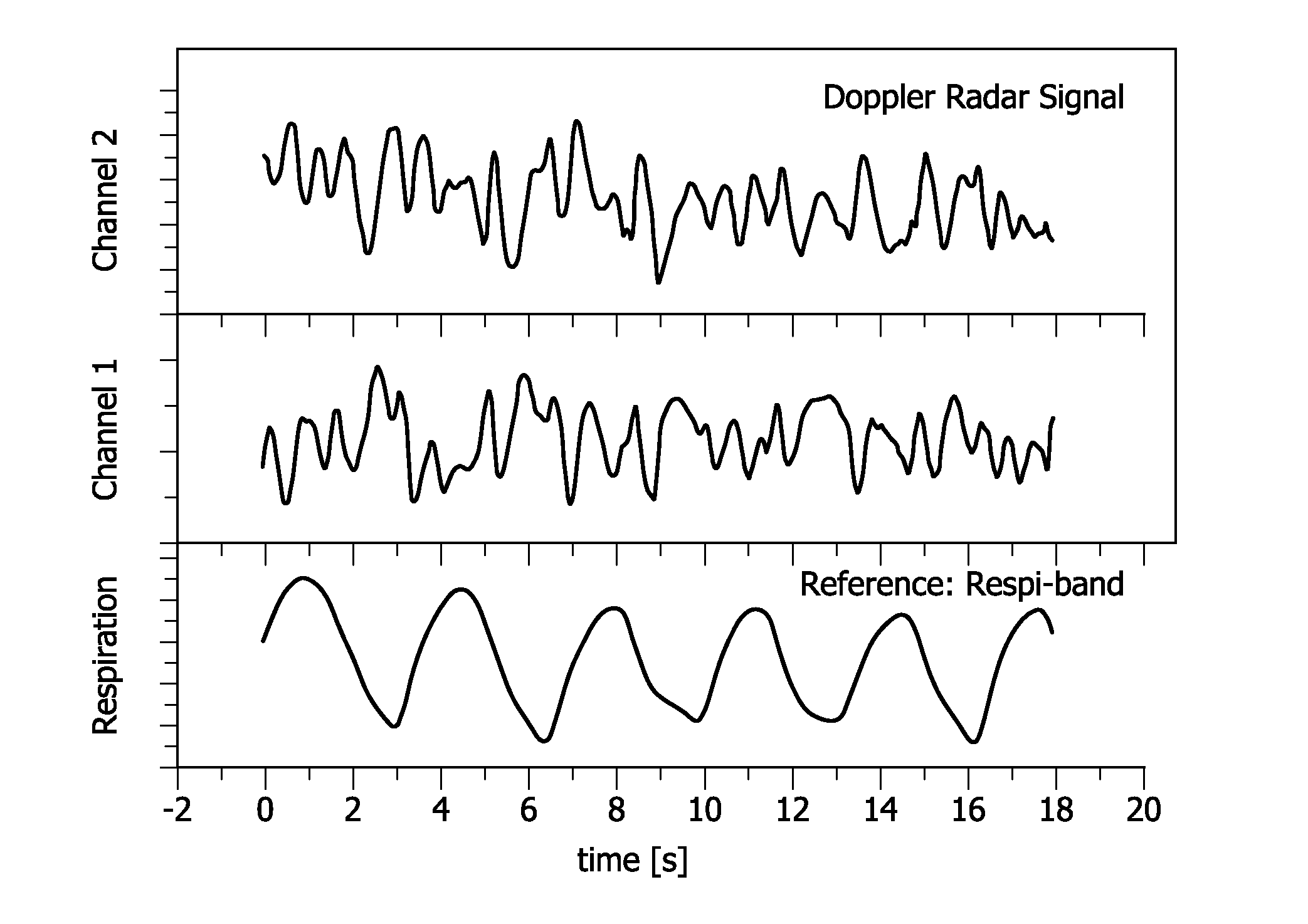
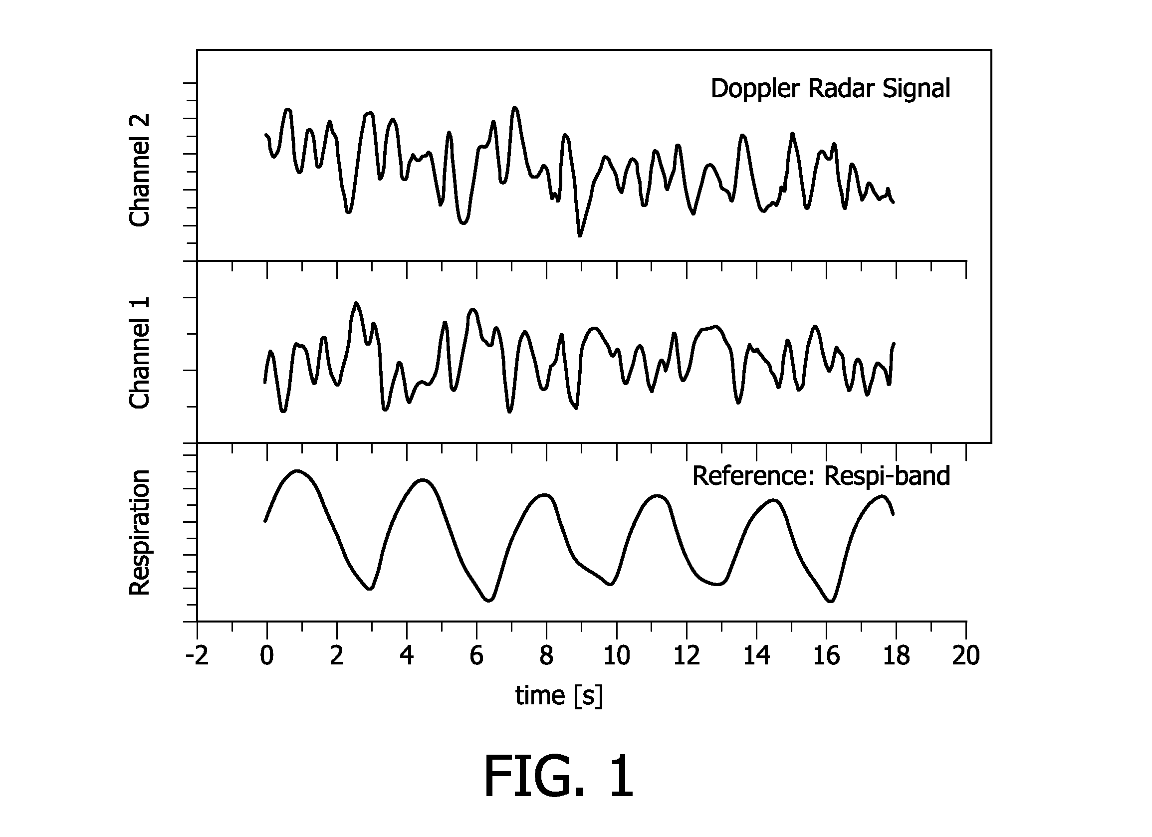
[0042]The two sensor signals coming from a two-channel Doppler radar sensor 12 can be modeled by the following equations:

[0043]x1⁡(t)=a·∑k=1N⁢⁢1Dk⁡(t)γ⁢cos⁡(Θk⁡(t))(1)x2⁡(t)=b·∑k=1N⁢⁢1Dk⁡(t)γ⁢cos⁡(Θk⁡(t)+2⁢Φ1)(2)

[0044]The cosine factors represent the local amplitudes of the reflected electromagnetic waves. The signal amplitudes a and b differ, because of different sensitivities of the separate channels. The influence of the changing sensor / target distances Dk(t) is modeled by an exponential factor γ. The phase difference 2Φ1 is determined by the specific Doppler sensor used. The timely varying phase Θk(t)

[0045]Θk⁡(t)=4⁢πλ⁢(∫0t⁢vk⁢(t′)⁢ⅆt′+Ξk)(3)

[0046]is related with the Doppler effect as a sum of signals from N reflectors moving with velocity components vk(t) relevant for the Doppler shift and the sensor / reflector distance Ξk for t=0. In the following, a single moving reflector is analyzed, which means that the functions D(t) and Θ(t) are simplified. Sensor / reflector distance D(t) a...


PUM


Abstract

Respiration of a patient is detected by emitting an electromagnetic signal towards the patient; receiving a reflected electromagnetic signal reflected from the patient; converting the reflected electromagnetic signal, yielding a first signal; phase-shifting the reflected electromagnetic signal and converting the phase-shifted reflected electromagnetic signal, yielding a second signal; determining a first vector being defined by the time derivatives of the first signal and the second signal, for a common first point in time; determining a second vector being defined by the time derivatives of the first signal and the second signal, for a common second point in time; and calculating the scalar product of the normalized first vector and the normalized second vector as an indicator value for a change from expiration to inspiration of the patient or vice versa. A change from expiration to inspiration of the patient or vice versa is preferably indicated if the indicator value is below a threshold value, preferably below a value of 0. In this way, respiration is monitored contactlessly and remotely based on the Doppler radar principle which is reliable and easy to handle.

Description

FIELD OF THE INVENTION[0001]The invention relates to the field of respiration monitoring of a patient, and especially to a method and a device for reliable breath-to-breath detection of inspiration / expiration for contactless remote respiration monitoring based on the Doppler-Radar principle.BACKGROUND OF THE INVENTION[0002]In a clinical environment, observing respiratory activity (breathing frequency) is highly relevant. Pulse and respiration are one of the most important basic vital signs to assess the health status of a patient. In intensive care unit (ICU) settings, pulse and respiration are routinely measured via ECG electrodes from the electrocardiogram, and the measured thorax-impedance changes during breathing activity, respectively.[0003]Doppler radar sensors have been identified as a promising technology for contactless measurements of respiration and cardiac activity. A large extent of research activities has been focused on Radar Systems at frequencies above 60 GHz. Today...

Claims


Application Information

Patent Timeline
Patent Type & Authority Patents(United States)
IPC IPC(8): G01S13/88G01S7/35A61B5/00A61B5/113A61B5/08A61B5/05G01S13/58
CPCA61B5/113G01S13/88A61B5/0816A61B5/7239G01S13/583A61B5/05G01S7/352A61B5/0507
Inventor MUEHLSTEFF, JENSPINTER, ROBERTMORREN, GEERT GUY GEORGES
Owner KONINK PHILIPS ELECTRONICS NV
Why Eureka
Try Eureka