Vial adaptor and manufacturing method therefor

a technology of adaptor and vial, which is applied in the direction of liquid bottling, medical devices, packaging goods, etc., can solve the problems of difficult manufacturing of internal passages/conduits, blockage or partially blockage of grooves, etc., and achieves convenient releasable attachment mechanisms, prevent human error, and facilitate manipulation and use.

Active Publication Date: 2014-10-28
ELCAM MEDICAL AGRICULTURAL COOPERATIVE ASSOCIATION LIMITED
View PDF65 Cites 85 Cited by
  • Summary
  • Abstract
  • Description
  • Claims
  • Application Information

AI Technical Summary

Benefits of technology

[0010]When the vial is inserted into the crown, a plunger locking mechanism of the injector is deactivated to allow withdrawal of medication from the vial and ejection of fluid back into the vial (or into a different vial if seated properly in the adaptor). Removal of the vial from the vial adapter will move the interior part in the vial removal direction locking the plunger locking mechanism to prevent ejection of fluid from the injector.
[0011]The vial adapter provides a convenient releasable attachment mechanism intermediate the vial and injector, and additionally provides easy manipulation and use as it is activated automatically upon vial insertion and prevents the possibility of human error.
[0012]It is a particular feature of the vial adaptor of the present invention that it is useable in combination with a conventional drug vial and an appropriate injector, to prevent accidental ejection of medication at inappropriate circumstances, however allows a liquid to be withdrawn from a first vial and ejected into the same or a different vial when the vial is seated (positioned) appropriately in the adaptor.
[0016]According to another aspect, the present invention relates to a bi-functional stopper-piercing member (hereinafter also referred to as a “spike”) that provides a conduit for withdrawing fluid from a vial while allowing ambient air to enter to neutralize pressure in the vial via another conduit. The conduits are internal to the spike and thus cannot be blocked, or partially blocked, by an external member, such as the vial's stopper. The conduits are preferably spaced apart to the extent possible, to reduce the possibility of air, which tends to form bubbles when entering the vial, from entering the fluid withdrawal conduit. For this purpose, the ends of the conduits that pass into the vial are preferably located at different heights along the spike and face in opposite directions. Preferably, the outlet of the air conduit is adjacent the piercing end (tip) of the spike while the end of the fluid withdrawal conduit is set back from the spike's tip. At the non-piercing end of the spike there is preferably a base that aids in connecting the spike to the remainder of the vial adaptor. Typically, the conduits are parallel to each other and the longitudinal axis of the spike.
[0018]According to yet another aspect, the present invention relates to a method of producing a dual-conduit stopper-piercing member, which allows longitudinal thermal expansion and lateral stability to the mold pins that define the conduit during the molding process.

Problems solved by technology

A possible issue with such grooves is that the typically elastomeric, i.e. resilient, stopper may block or partially block the grooves.
On the other hand, internal passages / conduits can be difficult to manufacture due to the small size and possibility of buckling of the mold pins creating the conduits as a result of temperature change, and / or manufacturing design, during the manufacturing process.

Method used


Image

  • Vial adaptor and manufacturing method therefor
  • Vial adaptor and manufacturing method therefor
  • Vial adaptor and manufacturing method therefor

Examples


Embodiment Construction

[0032]The following detailed description of the invention refers to the accompanying drawings. Dimensions of components and features shown in the figures are chosen for convenience or clarity of presentation and are not necessarily shown to scale. Wherever possible, the same reference numbers will be used throughout the drawings and the following description to refer to the same and like parts.

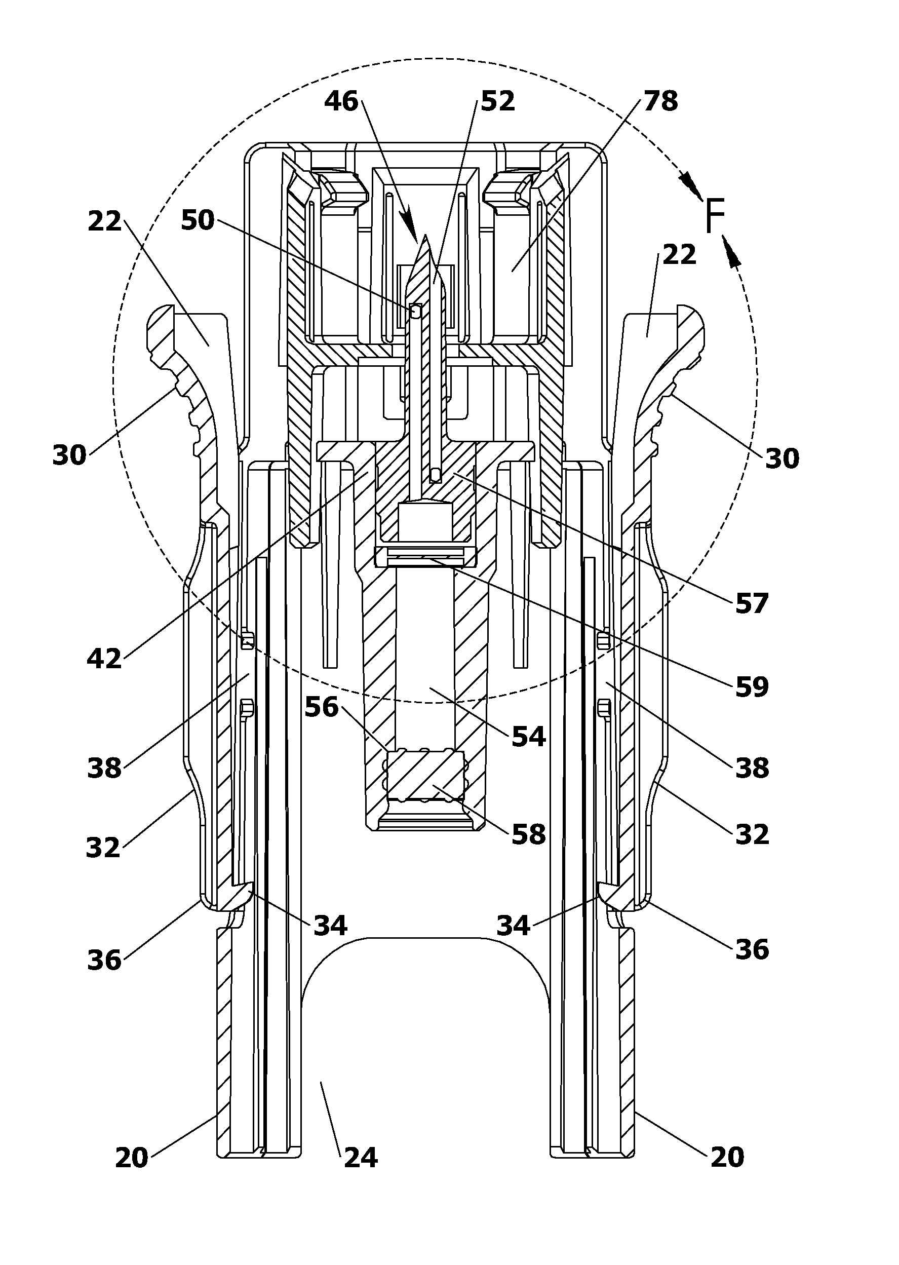
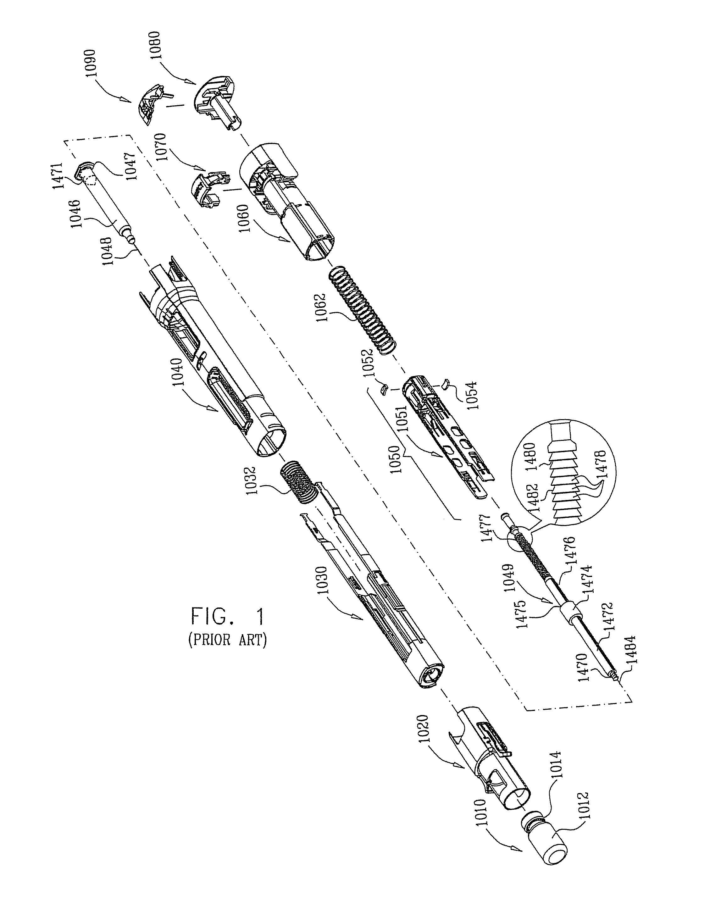
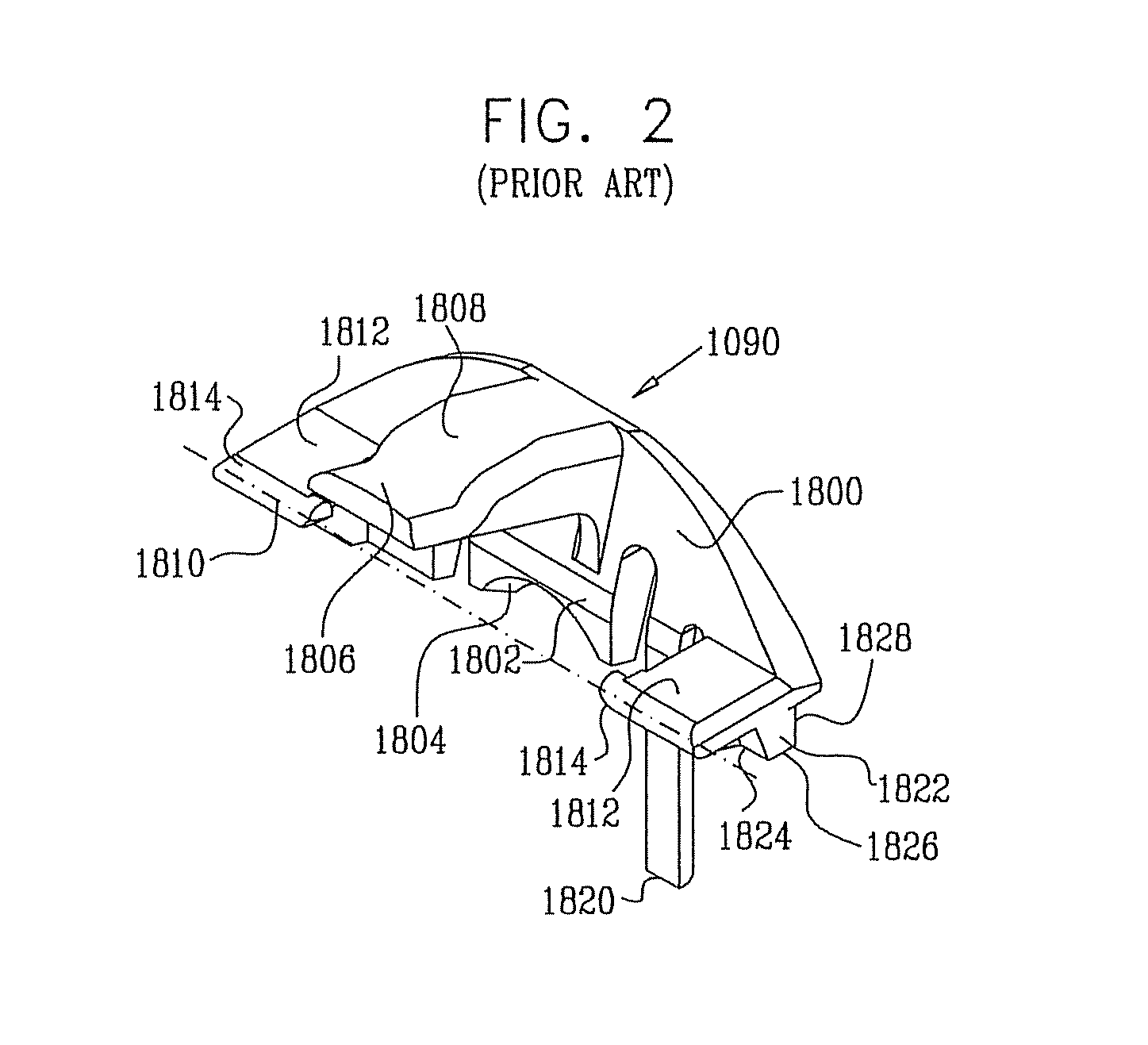
[0033]FIGS. 1 and 2 illustrate elements of a prior art injection device composed of an injector 1008; a typical container (herein after “drug vial” or “vial”; and designated as 1010); and a vial adaptor 1020 for connecting between the injector and vial. For understanding the vial adaptor of the present invention, designated with reference numeral 10, vial 1010 and injector 1008 will first be briefly described. It should be understood that the below described vial and injector are merely examples of a vial and an injector with which the present vial adaptor can be used.

Vial:

[0034]In FIG. 1 it i...


PUM

PropertyMeasurementUnit
diameteraaaaaaaaaa
pressureaaaaaaaaaa
axial movementaaaaaaaaaa

Abstract

A vial adaptor for releasably holding a vial (1010) and releasable connection to an injector (1008) comprising: a dual-sleeved member (11) comprising a forward facing sleeve (12) and a rearward facing sleeve (16) adapted to operably engage a front end of a forward housing (1040) of said injector (1008), and comprising a vial stopper piercing member (46); and a vial engaging element (60) adapted to slidingly translate within said forward facing sleeve (12) and releasibly hold said vial (1010) in a position whereby said vial stopper piercing member (46) pierces a stopper of said vial (1010), said vial engaging element (60) adapted to allow forward movement of a plunger of said injector (1008) when said vial (1010) is in said position. In other aspects, a vial-stopper piercing spike and a method of manufacturing same is described.

Description

FIELD OF THE INVENTION[0001]The present invention relates to an appliance for administering a medication, in particular a vial adaptor and a vial stopper-piercing member therefor and method of manufacturing the member.BACKGROUND OF THE INVENTION[0002]It is conventional to store drugs, vaccines, medicaments, solutions and the like (hereinafter, “medication(s)”) in a sealed vial or other similar container for later use. Such medications may be stored in a dry or powdered form and reconstituted in liquid form for later use, by adding a solvent, for example; alternatively, the medication may be stored in a vial in a liquid form.[0003]A conventional vial for storing medication has an open end, a radial rim surrounding the open end, a planar rim portion that overlies the vial rim, and a reduced diameter neck portion adjacent the rim. Commonly, such vials are closed by an elastomeric stopper, or other pierceable closure, which is pierced by a syringe.[0004]Vial adaptors, which are disposed...

Claims


Application Information

Patent Timeline
Patent Type & Authority Patents(United States)
IPC IPC(8): A61J1/20A61M5/00A61M5/20A61M5/178A61M5/28A61M5/24
CPCA61M5/1782A61J2001/201A61J2001/2055A61J2001/2065A61J1/2096A61M5/2033A61J1/1418A61J1/201A61J1/2055A61J1/2065
Inventor RADAY, LIORMARELI, LIORCARMEL, EHUDDAILY, DAVIDKEENAN, GUY
Owner ELCAM MEDICAL AGRICULTURAL COOPERATIVE ASSOCIATION LIMITED
Why Eureka
Try Eureka