Supercharge Your Innovation With Domain-Expert AI Agents!

Flexible inlay strips and method of manufacturing the same

a technology of flexible inlay strips and inlay, which is applied in the direction of thin material handling, lamination ancillary operations, instruments, etc., can solve the problems of inability to bend the same way, reduce the availability of abalone, oyster, snail and other mollusk shell materials, and the use of organic shell materials for inlay purposes. , to achieve the effect of less tim

Active Publication Date: 2014-10-28
RYAN KEVIN
View PDF5 Cites 0 Cited by
  • Summary
  • Abstract
  • Description
  • Claims
  • Application Information

AI Technical Summary

Benefits of technology

The present invention is about flexible purfling strips which can be easily bent and placed in curved channels in both the top and side of an instrument. The strips are made by layering a binding material over an ornamental layer made of non-organic or synthesized materials, such as GEMLAM. The binding material allows the strips to bend longitudinally and transversely. The flexible purfling strips can be installed faster than traditional purfling strips and can be attached end-to-end to create an entire unit of ornamental purfling / wood purfling in a single step. The result is faster and easier installation with the appearance of a flexible, durable finish.

Problems solved by technology

), the use of these organic shell materials for inlay purposes is problematic because of the difficulty in obtaining shell pieces of sufficient thickness.
The practical impact of these restrictions is the decrease in the availability of abalone, oyster, snail and other mollusk shell materials.
One of the limitations of the known purfling strips is that the strips are not flexible and cannot be bent in the same manner as the binding.
The lack of flexibility is problematic when it is desired for the inlay to be curved, which is typically the case for purfling used on instruments.
However, this process is very time consuming and labor-intensive.
However, there are disadvantages associated with this method as well.
The machinery required for this method is expensive, and the programming and milling time for each shape can require substantial time.
The inventory requirements for the inlay material can also be difficult for smaller manufacturers, because different instrument models and configurations utilize different shapes of inlay material.
This method also results in greater waste of inlay material than the previously described method and the method taught in the '053 Patent and further disclosed herein.
Each of the processes described above may be time consuming for another reason.

Method used


Image

  • Flexible inlay strips and method of manufacturing the same
  • Flexible inlay strips and method of manufacturing the same
  • Flexible inlay strips and method of manufacturing the same

Examples


first embodiment

[0045]In the method, a thin sheet (approximately 0.005″ thick) of binding material, such as the 3M vinyl tape discussed above, acetate or polyurethane, is affixed to the back side of the separated strips of ornamental blank material, thereby creating a layered configuration comprising, from bottom to top, the rigid substrate 52, the ornamental layer (second layer 38) and the binding material layer (first layer 36) At this point, the strips of the ornamental blank have been milled into the proper width (generally 0.050″) but the strips remain glued to the rigid substrate 52. The inventor herein has found that the 3M vinyl tape discussed above, acetate, or polyurethane are the preferred binding materials because each possesses several critical properties: each are flexible enough to bend but stiff enough to retain a linear path, are impervious to the water bath required for removal of the ornamental blank strips from the rigid substrate 52, and each material holds fast to the ornament...

second embodiment

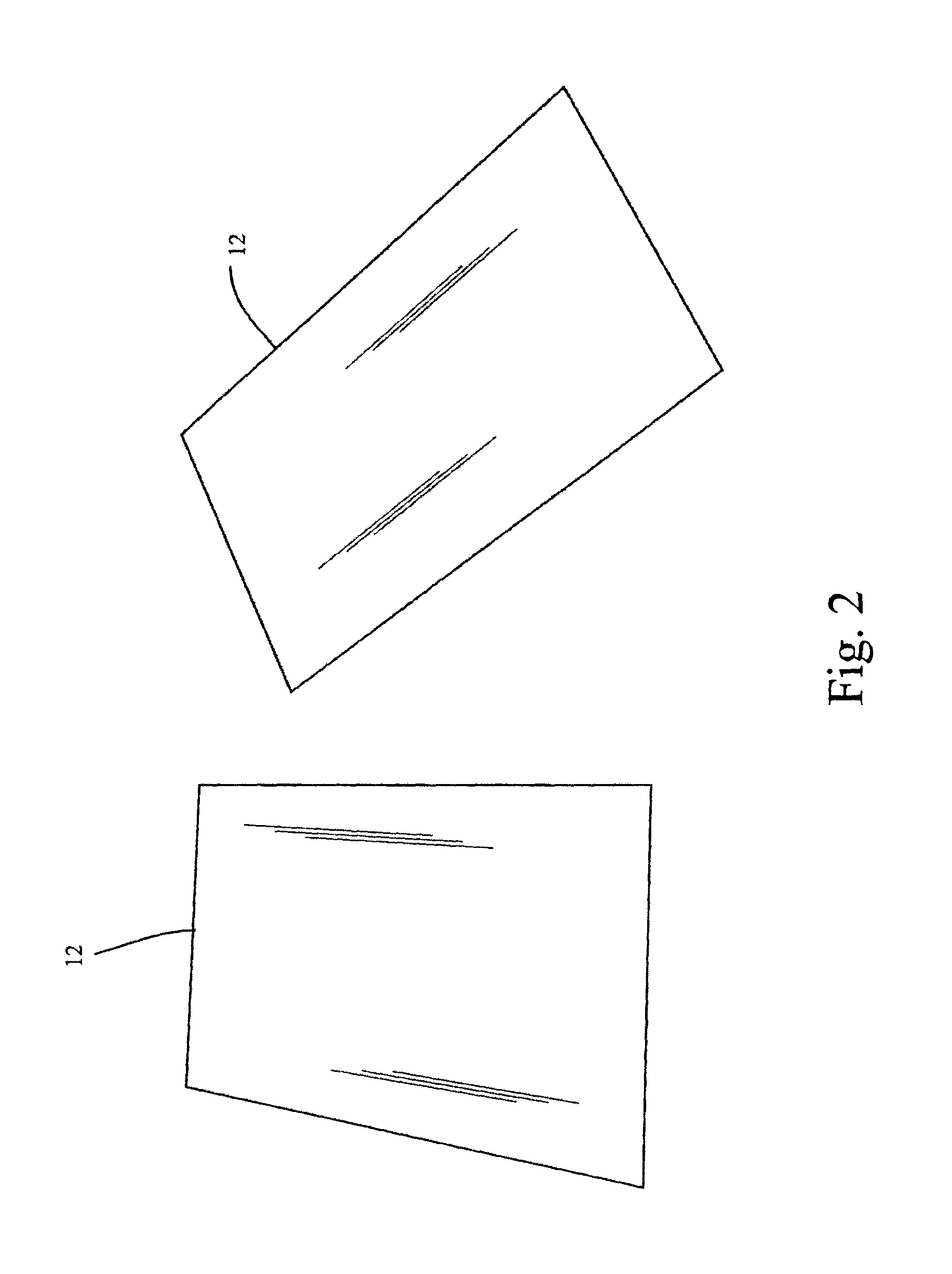
[0049]In the manufacturing method, as in the embodiment disclosed above, a sheet 12 of ornamental blank material, such as ABALAM or a sheet 12′ of an inorganic material, such as synthetic opal, is glued exposed face down with hide glue or other water soluble adhesive to a rigid substrate 52 such as a sheet of Masonite or similar material, typically having dimensions of W×L. As illustrated in FIG. 11, the glued assembly is thereafter cut into strips 14, but not cutting all of the way through the rigid substrate 52. After being cut, strips 14 are removed from the rigid substrate 52 by dissolving the water soluble adhesive. The strips 14 are thereafter mounted to a second rigid substrate 52′ with a water soluble adhesive, such that the strips are arranged in parallel with one another, the parallel strips defining a long axis oriented along length L of the rigid substrate 52′. The sides of adjacent strips 14 are mounted such that adjacent strips abut one another in direct contact. When ...


PUM

PropertyMeasurementUnit
thicknessaaaaaaaaaa
angleaaaaaaaaaa
lengthsaaaaaaaaaa

Abstract

A method of fabricating an ornamental purfling strip which has sufficient flexibility to be placed within a curved configuration. The ornamental purfling strips are sufficiently flexible to be placed, as a single unit, in curved channels which require the strip to bend. The flexibility results from a laminated structure comprising a layer of binding material overlain by an ornamental layer, with an adhesive or bonding agent attaching the layers together. The ornamental layer comprises a plurality of precisely placed breaks along its length. The binding material retains the individual fragments of the ornamental layer in the strip, but because the binding material comprises a flexible material, the layer of binding material is sufficiently flexible to allow the purfling strip to flex longitudinally and transversely. The ornamental layer may comprise organic shell material or synthetic materials such as synthetic opal.

Description

CROSS-REFERENCE TO RELATED APPLICATION[0001]This is a Continuation-In-Part application of U.S. patent application Ser. No. 13 / 245,458 which was filed on Sep. 26, 2011, for which application this inventor claims domestic priority.BACKGROUND OF THE INVENTION[0002]The present invention generally relates to the construction of finely crafted wooden objects, such as musical instruments, cutlery and curios, in which the wooden object includes an inlay portion for ornamentation or functional purpose, such as inlay which forms an ornamental border adjacent to the outside edges of an instrument. An inlay is a material set within a depression or channel formed in a matrix material where, once installed, the top surface of the inlay is generally flush with the surface of the matrix material. Although many different materials may be utilized as the inlay material, organic shell materials such as abalone, oyster and snail have traditionally been utilized as the inlay material because of the lust...

Claims


Application Information

Patent Timeline
Patent Type & Authority Patents(United States)
IPC IPC(8): B32B38/00B32B3/14B44C1/26B44C3/02B32B9/00
CPCB44C1/26B44C3/02Y10T428/192Y10T428/183Y10T428/19Y10T428/2495Y10T428/17
Inventor RYAN, KEVIN
Owner RYAN KEVIN
Features
  • R&D
  • Intellectual Property
  • Life Sciences
  • Materials
  • Tech Scout
  • Unparalleled Data Quality
  • Higher Quality Content
  • 60% Fewer Hallucinations
Learn More