Stream signal transmission device and transmission method

a transmission device and signal technology, applied in data switching networks, two-way working systems, frequency-division multiplexes, etc., can solve problems such as temporal incongruity, and achieve the effects of reducing transmission delay fluctuation, and absorbing transmission time fluctuation

Inactive Publication Date: 2014-10-28
NEC CORP
View PDF13 Cites 6 Cited by
  • Summary
  • Abstract
  • Description
  • Claims
  • Application Information

AI Technical Summary

Benefits of technology

[0012]In the present invention, delay control is performed in which an output time is determined by adding a predetermined fixed delay to a time indicated by a time code attached to a received stream signal, and the received stream signal is output after holding the received stream signal up to the output time. Therefore, it is possible to absorb fluctuation in transmission time within the fixed delay, maintain the output time to a set constant value corresponding to the fixed delay, eliminate transmission delay fluctuation with a fast change such as network jitter with high accuracy, and synchronize a plurality of streams.

Problems solved by technology

If network transmission times of all streams are not identical, temporal incongruity is generated when the streams are switched on the reception side.

Method used


Image

  • Stream signal transmission device and transmission method
  • Stream signal transmission device and transmission method
  • Stream signal transmission device and transmission method

Examples


first exemplary embodiment

[First Exemplary Embodiment]

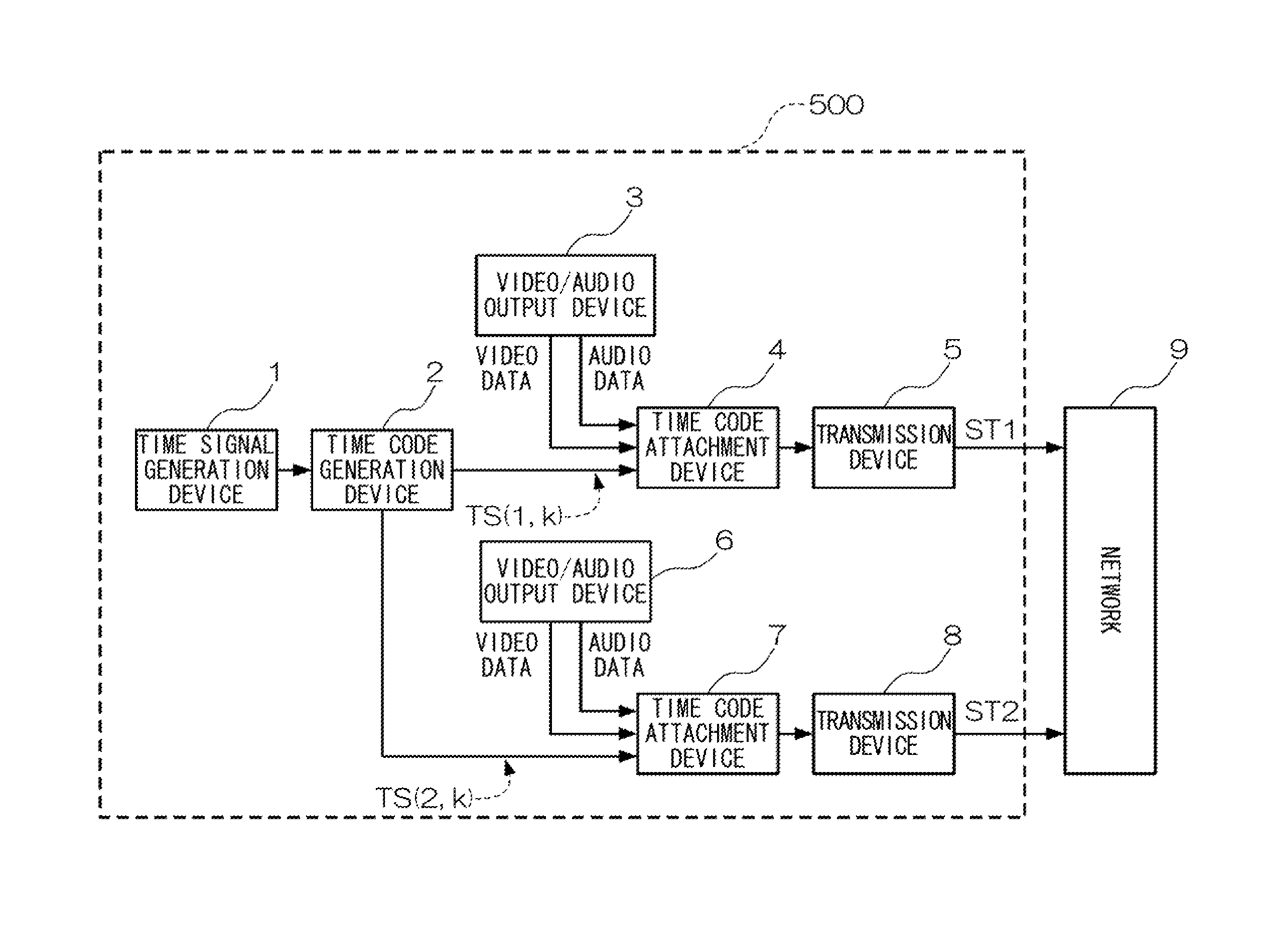
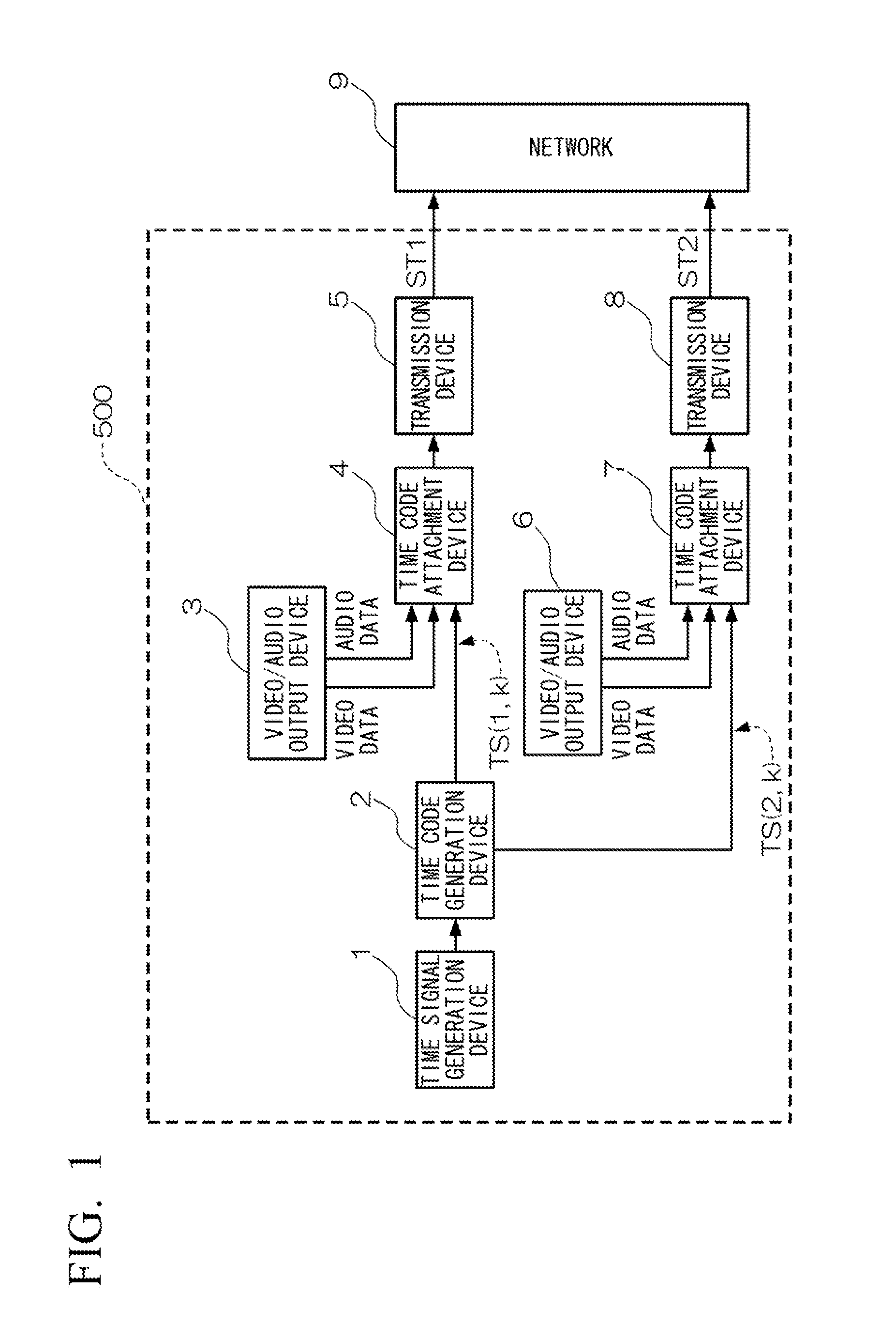
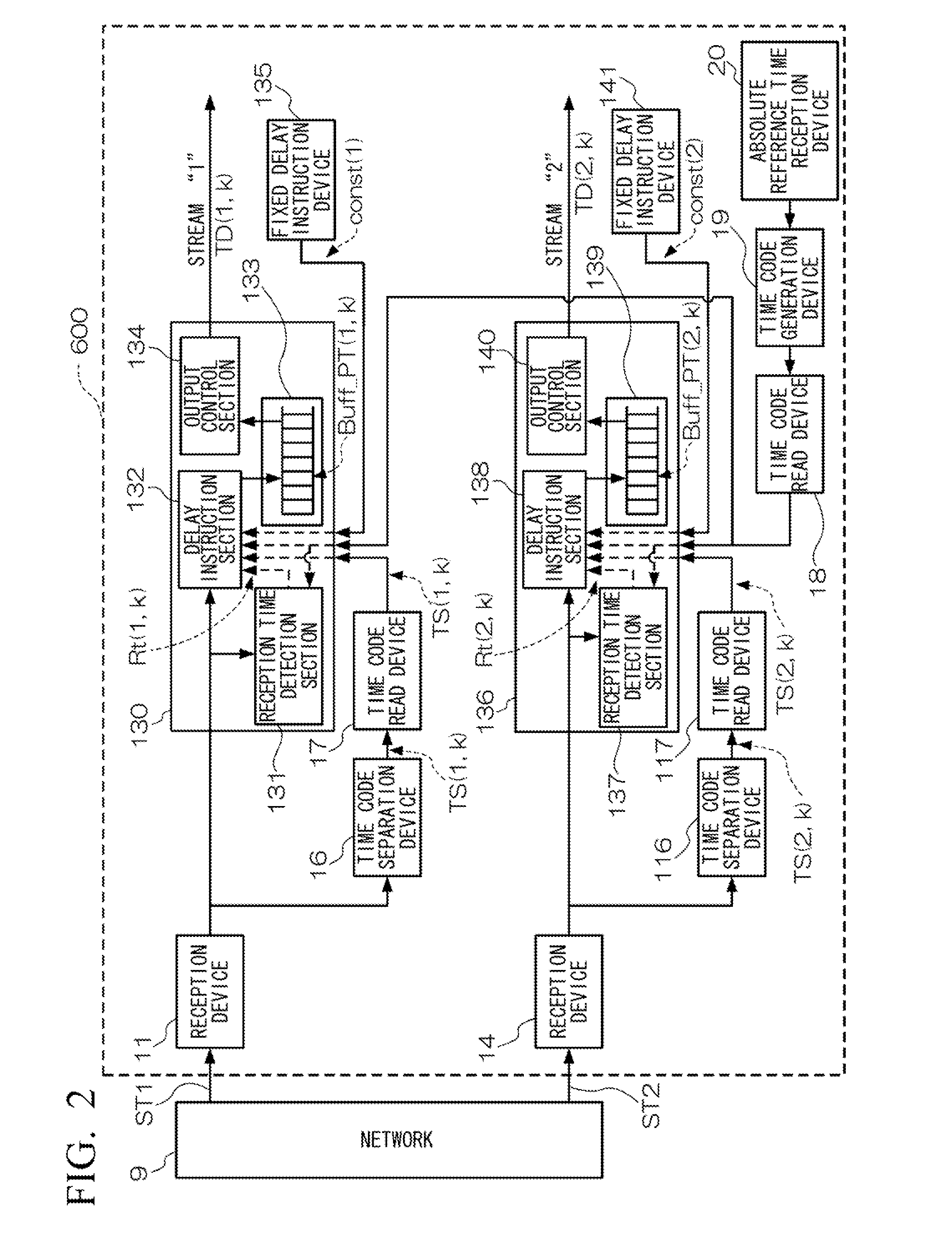
[0022]A first exemplary embodiment of the present invention will be described based on the drawings. A stream signal transmission device of the first exemplary embodiment of the present invention is shown in FIGS. 1 and 2. The stream signal transmission device of the first exemplary embodiment of the present invention is configured by a transmission side system-A 500 shown in FIG. 1, a reception side system-A 600 shown in FIG. 2, and a network 9 shown in FIGS. 1 and 2. However, it can be construed that an exemplary aspect of the present invention is configured by only the reception side system-A 600, it is configured by the transmission side system-A 500 and the reception side system-A 600, or it is configured by one or more sets of the transmission side system-A 500 and / or the reception side system-A 600. It is to be noted that the present exemplary embodiment can be configured to partially or entirely use software control using a central processing unit...

second exemplary embodiment

[Second Exemplary Embodiment]

[0055]A stream signal transmission device of a second exemplary embodiment of the present invention is shown in FIGS. 3 and 4. The stream signal transmission device of the second exemplary embodiment of the present invention is configured by a transmission side system-B 510 shown in FIG. 3, a reception side system-B 610 shown in FIG. 4, and a network 9 shown in FIGS. 3 and 4. It is to be noted that in the present exemplary embodiment, the same configurations as those of the first exemplary embodiment described with reference to FIGS. 1 and 2 are denoted by the same reference symbols. In the present exemplary embodiment, one piece of video / audio is transmitted from the transmission side system-B 510 shown in FIG. 3 to the network 9 as two video / audio streams. The reception side system-B 610 shown in FIG. 4 selects and outputs one stream from among the received two video / audio streams. By adopting these configurations, the present exemplary embodiment cons...


PUM


Abstract

Provided is a stream signal transmission device that can eliminate transmission delay fluctuation with a fast change such as network jitter with high accuracy and synchronize a plurality of streams. The stream signal transmission device includes at least one reception unit that receives a stream signal to which a time code is attached from a network, at least one extraction unit that extracts the time code from the stream signal received by the reception unit, and at least one delay control unit that determines an output time by adding a predetermined fixed delay to a time indicated by the time code extracted by the extraction unit, and outputs the stream signal received by the reception unit after holding the stream signal up to the output time.

Description

TECHNICAL FIELD[0001]The present invention relates to a stream signal transmission device and a transmission method to be preferably used when video and / or audio streams are transmitted via a network.BACKGROUND ART[0002]Recently, video and / or audio stream transmission via a network such as an Internet protocol (IP) network has been possible as a result of remarkable development of communication technology. In the video and / or audio stream transmission via the network such as the IP network, it is possible to realize transmission of video streams and audio streams at a low cost as compared with television broadcasting.[0003]However, in the video and / or audio stream transmission via the network, the transmission time from a transmission side to a reception side is significantly different depending on a used band, a network congestion state, and / or a network path difference. The transmission time also fluctuates depending on network jitter or the like. Because of fluctuation in the tra...

Claims


Application Information

Patent Timeline
Patent Type & Authority Patents(United States)
IPC IPC(8): H04L12/28H04L12/26H04N21/242H04N21/43H04B7/00H04N7/24H04N7/173H04N21/236H04N21/238H04N21/435H04N21/44H04N21/83
CPCH04N21/242H04N7/24H04N21/4307H04N21/43072
Inventor HASHIMOTO, KIYOSHI
Owner NEC CORP
Why Eureka
Try Eureka