Device for transporting objects

a technology for transporting objects and objects, applied in the field of transporting objects, can solve problems such as difficult removal, damage to objects, and disordered objects

Inactive Publication Date: 2014-11-04
PAUL HETTICH
View PDF37 Cites 9 Cited by
  • Summary
  • Abstract
  • Description
  • Claims
  • Application Information

AI Technical Summary

Benefits of technology

[0004]Transport devices are known in which the objects are placed in fixed magazines. By this means the objects can be positioned exactly for a subsequent removal and are additionally protected from damage. However, such transport devices are not flexible and the magazines can only be used for objects of predetermined size.
[0006]It is therefore the object of the present invention to provide a device for transporting objects which ensures secure transport of objects with a simple structure and can be adapted flexibly to different-sized objects.
[0007]According to the invention, the device for transporting objects comprises at least one middle wall section between the outer walls, which is displaceably mounted on a floor guide and can be fixed at different distances from an outer wall. As a result, a plurality of magazines can be formed between the displaceable middle wall section and an outer wall, in which corresponding objects can be placed. In doing so, the object is placed with one end section in a receiving hopper on an outer wall and on the opposite side in a receiving hopper on the middle wall section. If the length of the objects to be placed changes, for example, as a result of a changeover in production, the device can be further used, merely the middle wall section is displaced and adapted in position to the length of the objects to be placed. By this means, a high degree of flexibility can be provided with a device for transporting objects, where the objects in the individual hoppers are disposed in exact positions and can then be gripped in an automated fabrication process.
[0009]For easy displacement of the wall sections, these can be guided on the floor on at least one rail. In this case, the at least one rail can be configured to be U-shaped in cross-section where at least one roller connected to the wall section is guided in the rail. This ensures smooth-running guidance and prevents canting of the wall sections. In order to improve the guidance of the wall sections, the wall section can have a carriage on the floor on which at least two rollers spaced apart from one another in the longitudinal direction of the rail are mounted on the carriage. If each displaceable wall section has at least two carriages on the floor side, which are guided on parallel rails, canting of the wall sections can be reliably avoided.
[0010]According to a preferred embodiment, each hopper has a floor section on which the lowest object rests with an end section. This ensures that the objects are positioned exactly in height and in addition weight forces can be removed via the wall sections to the frame or the rails. This can prevent the weight forces from acting on the guide elements such as the rollers in order to avoid damage at higher weight loads, in particular when placing metal components thereon.
[0012]In order to enable an adjustment process in a simple manner, the retaining elements can be configured as toothed racks, on which the wall sections can be fixed at predetermined positions. Locking positions can thus be predefined by means of the toothed racks so that the hoppers on the outer walls and the displaceable wall sections can be positioned exactly with respect to one another. The retaining elements in a first position can be out of engagement with the at least one displaceable wall section and in a second position fix the at least one wall section. For easy handling the retaining elements in the first and the second position can be engaged by means of a sliding block guide so that a single operator can execute an adjustment process.

Problems solved by technology

As a result, the objects are disordered and are difficult to remove in an automated fabrication process.
In addition, the objects can be damaged during transport and / or when filling the lattice boxes.
However, such transport devices are not flexible and the magazines can only be used for objects of predetermined size.
Transporting and retaining heavy objects is only possible to a limited extent with this structure.
Due to the frame-shaped configuration of the frame the accessibility from the side is made difficult.

Method used


Image

  • Device for transporting objects
  • Device for transporting objects
  • Device for transporting objects

Examples


Embodiment Construction

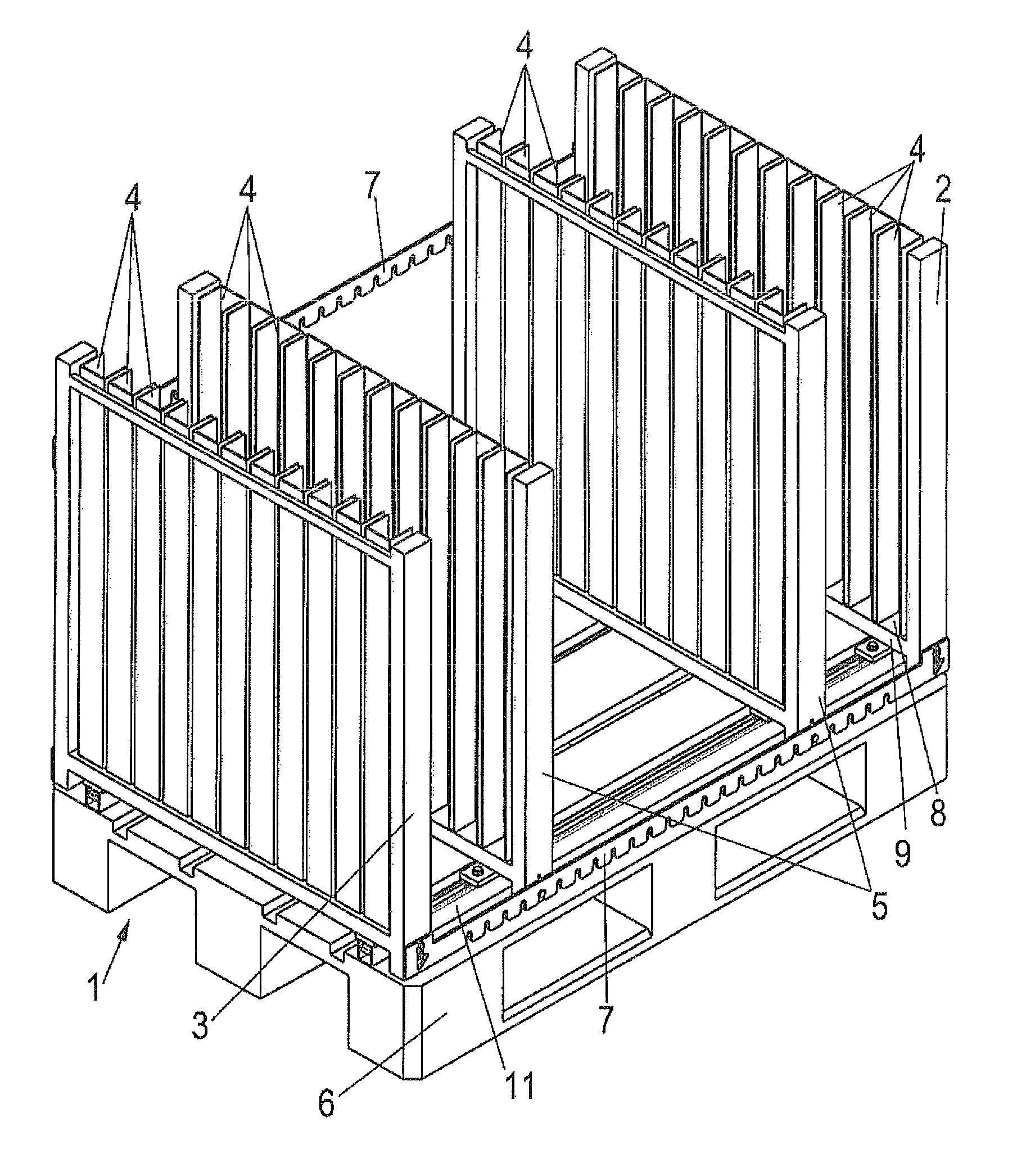
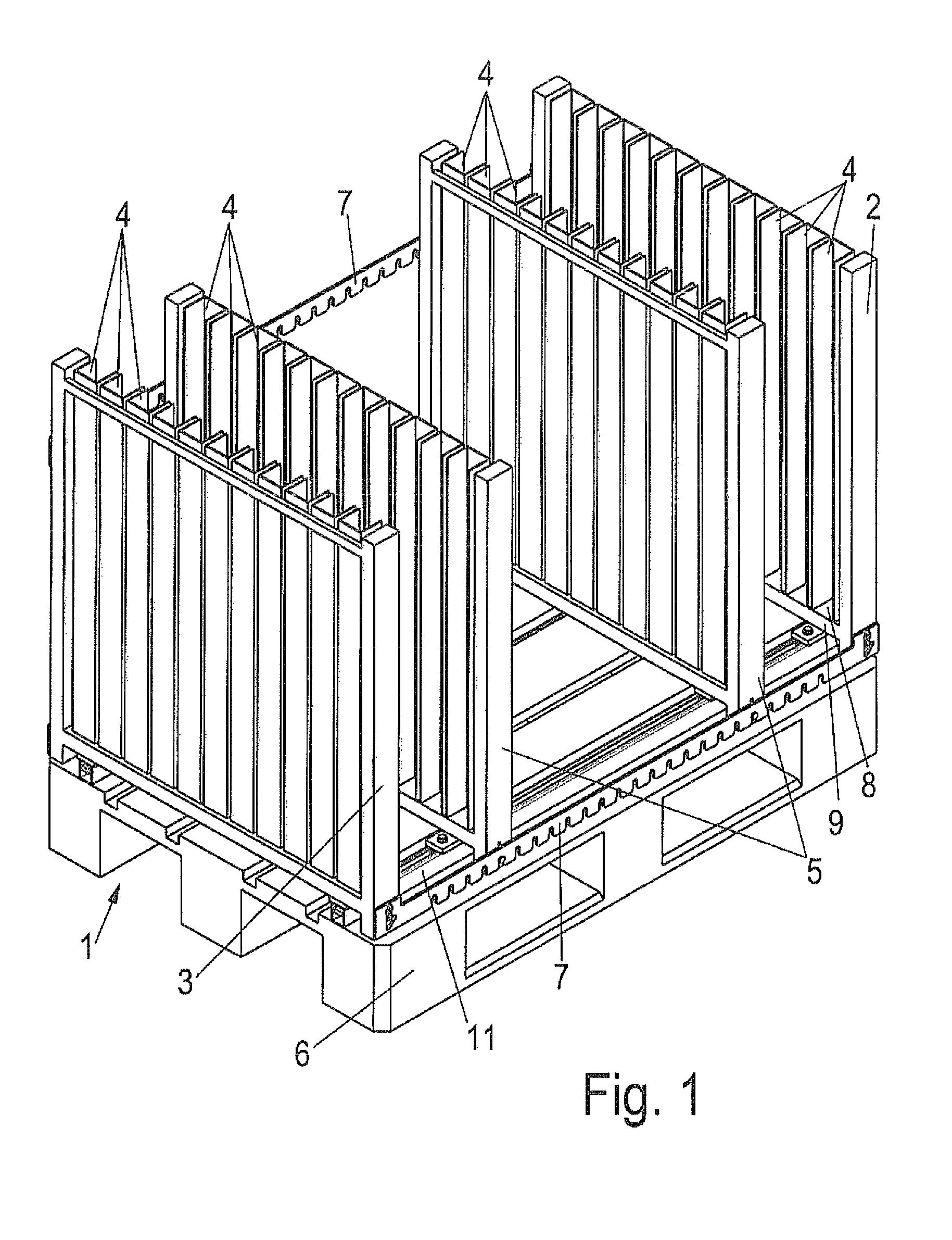
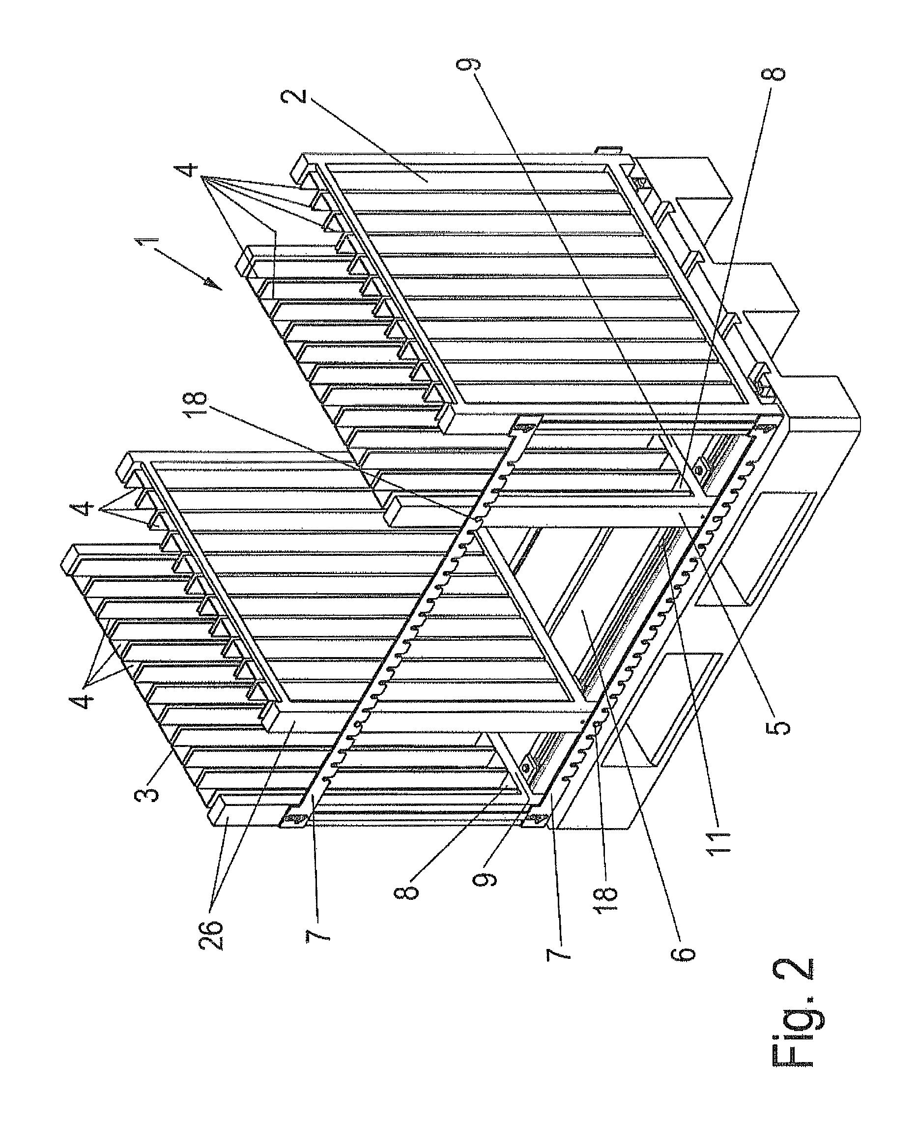
[0023]A device 1 for storing and transporting objects is substantially configured to be rectangular and comprises at opposite end faces outer walls 2 and 3, on which a plurality of receiving hoppers 4 are formed. Two wall sections 5 are provided between the outer walls 2 and 3, and which are mounted displaceably on the floor side. The wall sections 5 also have receiving hoppers 4 on one side or on both sides, which are disposed opposite the receiving hoppers 4 on the outer walls 2 and 3. As a result, an object, for example, a profile rail, can be inserted with a first end section in a receiving hopper 4 on an outer wall or 3 and with a second end section in a receiving hopper 4 on a wall section 5. The receiving hoppers 4 are formed by U-shaped profiles so that the end sections of the object are arranged in a protected manner.

[0024]The floor of the device 1 comprises a pallet 6 which is configured as a standardized Euro pallet and on which two rails 11 are mounted, which are spaced ...


PUM


Abstract

A device for transporting objects, in particular fittings, having a frame includes outer walls (2, 3) protruding upwards from a floor at opposite end faces, on which a plurality of receiving hoppers (4) are provided for placing a first end section of an object, and at least one middle wall section (5, 5′) protruding from the floor. A plurality of receiving hoppers (4) is provided thereon for placing a second end section of an object opposite the first end section. At least one middle wall section (5, 5′) is displaceably mounted on a floor guide and can be fixed at different distances from an outer wall (2, 3).

Description

CROSS-REFERENCE TO A RELATED APPLICATION[0001]The invention described and claimed hereinbelow is also described in German patent Application DE 20 2010 000 875.1 filed on Jan. 12, 2010. This German Patent Application, whose subject matter is incorporated here by reference, provides the basis for a claim of priority of invention under 35 U.S.C. 119 (a)-(d).BACKGROUND OF THE INVENTION[0002]The present invention relates to a device for transporting objects.[0003]Lattice boxes or pallet containers in which objects produced in production facilities are placed are known for the storage and transport of objects. As a result, the objects are disordered and are difficult to remove in an automated fabrication process. In addition, the objects can be damaged during transport and / or when filling the lattice boxes.[0004]Transport devices are known in which the objects are placed in fixed magazines. By this means the objects can be positioned exactly for a subsequent removal and are additionally ...

Claims


Application Information

Patent Timeline
Patent Type & Authority Patents(United States)
IPC IPC(8): A47F5/10A47F7/00A47B57/58A47B45/00B65D25/06B65D19/44A47G19/08B65G49/06A47F5/00
CPCB65D2519/00333B65D2519/0082A47F5/0093B65D19/44B65D2519/00666B65D25/06B65D2519/00164B65D2519/00631A47F7/0042B65D2519/00174A47F5/10A47B45/00B65G49/064A47B57/583A47B57/58
Inventor GERKENSMEIER, CHRISTIANHAMPKER, REINHARD
Owner PAUL HETTICH
Why Eureka
Try Eureka