Automatic flow blocking system for reverse pulse filter cleaning

a filter cleaning and reverse pulse technology, applied in the field of fluid bed coat, can solve the problems of affecting the cleaning effect, and preventing the flow of air, so as to achieve the effect of more reliable operation

Active Publication Date: 2014-11-04
SPRAYING SYST
View PDF11 Cites 19 Cited by
  • Summary
  • Abstract
  • Description
  • Claims
  • Application Information

AI Technical Summary

Benefits of technology

[0006]It is an object of the present invention to provide a process vessel having a reverse pulse air filter cleaning system adapted for more reliable operation.
[0008]A further object is to provide a process vessel having a reverse pulse air filter cleaning system of the above kind which is effective for sealing off the air plenum during the filter cleaning cycle.
[0010]Still a further object is to provide such a process vessel with a reverse pulse air filter cleaning system that is relatively simple in construction and reliable in operation.

Problems solved by technology

In many instances, the process occurring does not allow the flow of air to be stopped from the process vessel to the exhaust plenum.
This hampers the cleaning and often makes the reverse pulse method of filter cleaning ineffective.
This can occur for several reasons, but is normally attributed to the size the particles being cleaned, the frequency by which the filter can be cleaned, improper positioning and sizing of the compressed air nozzle, and an excessive air velocity across the filter element.
This large pressure differential hinders the venturi effect that draws air from the exhaust plenum and reduces the effectiveness of the air pulse.
Often these methods are impractical to implement and reduce efficiency of the process.

Method used


Image

  • Automatic flow blocking system for reverse pulse filter cleaning
  • Automatic flow blocking system for reverse pulse filter cleaning
  • Automatic flow blocking system for reverse pulse filter cleaning

Examples


Embodiment Construction

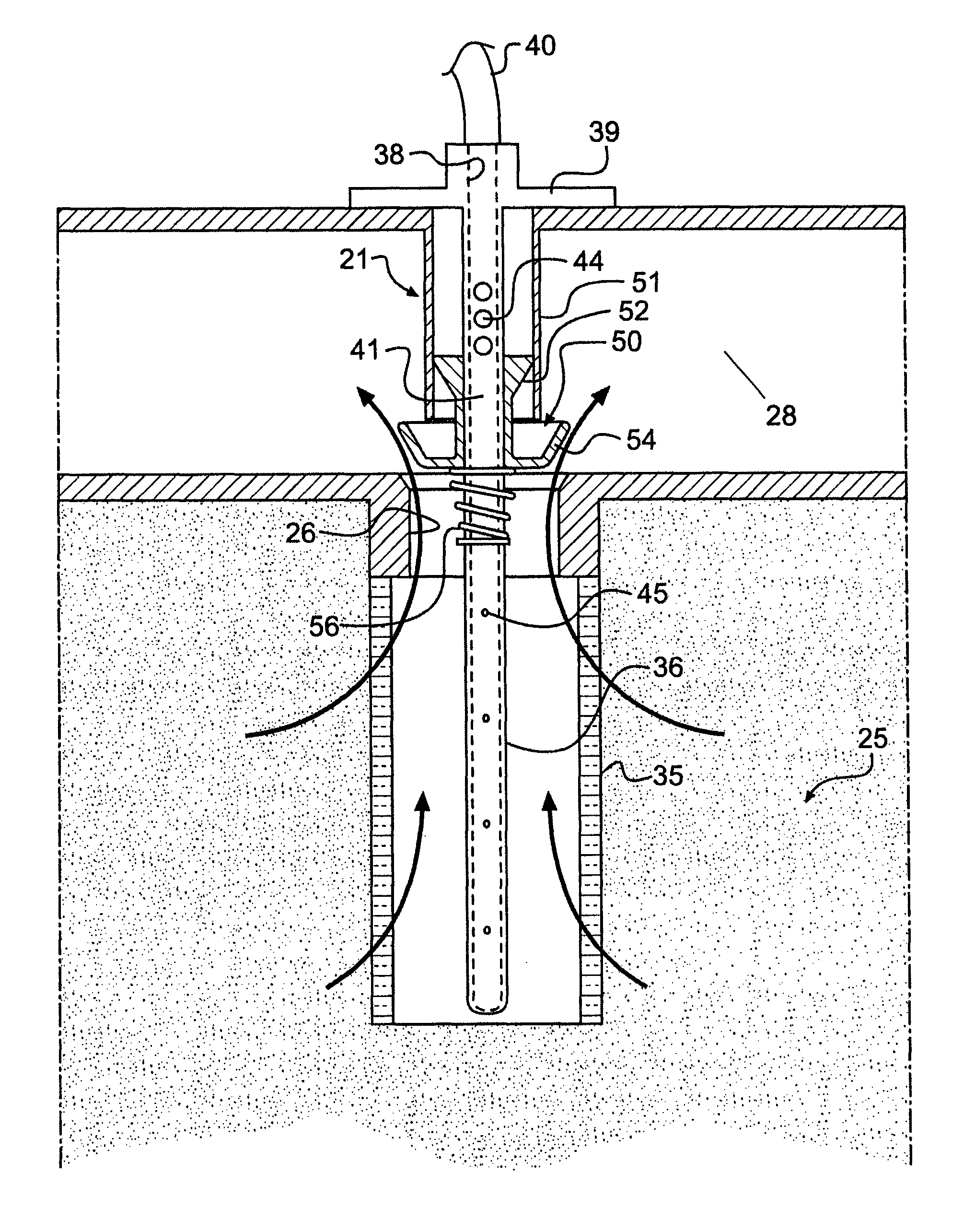
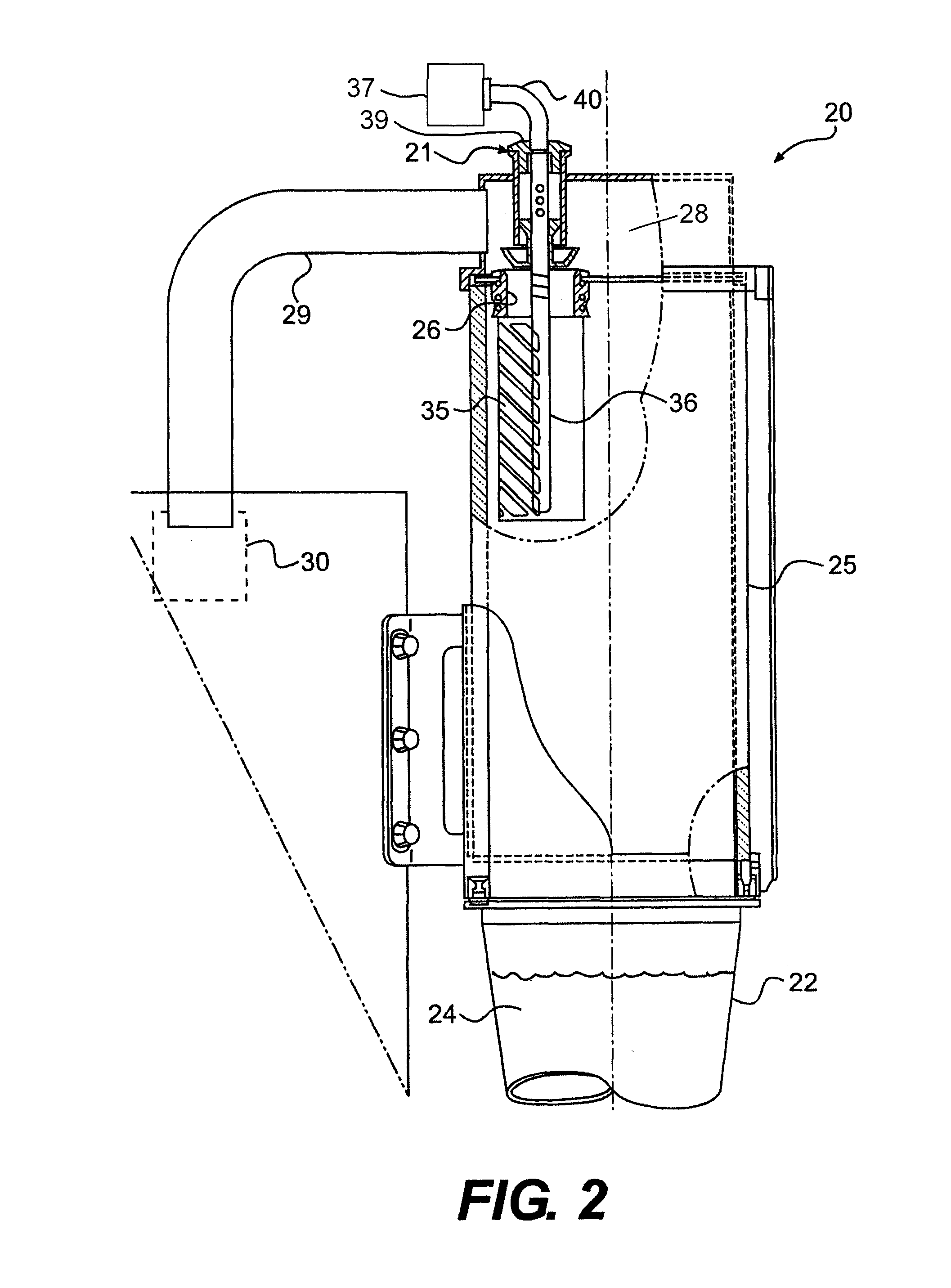
[0017]Referring now more particularly to FIGS. 2-4 of the drawings, there is shown an illustrative fluid bed dryer 20 having a reverse pulse air filter cleaning device 21 in accordance with the invention. It will be understood that the fluid bed dryer20 may be part of any of various types of known processing systems. The illustrated fluid bed dryer 20 includes an upwardly and outwardly opening bowl 22 which contains a bed of powder 24 and which communicates with an air inlet plenum from its underside. The powder containing bowl 22 is mounted in underlying relation to a process vessel 25 which has an exhaust port 26 at an upper end communicating with an exhaust plenum 28, which in turn communicates with a downwardly angled exhaust pipe 29. As it is known in the art, a blower 30 coupled to the exhaust pipe 29 can be operated to draw a negative pressure through the exhaust plenum 28, process vessel 25, and bowl 22 for drawing air upwardly through the bed of powder 24 for purposes of dr...


PUM

PropertyMeasurementUnit
lengthaaaaaaaaaa
sizeaaaaaaaaaa
pressureaaaaaaaaaa

Abstract

A powder processing system having a processing vessel into which powder is pneumatically supplied and an exhaust plenum that communicates with the processing vessel through an exhaust port. A filter is located at the exhaust port for filtering air borne powder from the air flow exiting the processing vessel, and a reverse pulse air filtering device is provided for selectively removing accumulated powder from the filter. The cleaning device includes a nozzle having a first portion within the air plenum and a second portion within the air filter, and a plunger is mounted on the first filter portion for movement to an exhaust port closing position as an incident to the direction of pressurized air through the first portion of the nozzle for enabling pressurized air from the second portion of the nozzle to thereupon be directed through the filter without hindrance of air exiting the processing vessel.

Description

CROSS-REFERENCE TO RELATED APPLICATIONS[0001]This patent application claims the benefit of U.S. Provisional Patent Application No. 61 / 312,535, filed Mar. 10, 2010, which is incorporated by reference.FIELD OF THE INVENTION[0002]The present invention relates generally to fluid bed coaters, dryers, granulators, and other processing equipment in which airborne particles must be separated from an air stream by means of one or more filter elements for retaining and collecting the particles to prevent them from entering the atmosphere or other process vessels. More particularly, the invention relates to a reverse pulse filter cleaning system for removing particulate matter that has accumulated on the filter element by means of periodic pulses of compressed air.BACKGROUND OF THE INVENTION[0003]In conventional fluid bed processing equipment 10 of the foregoing type, as depicted in FIG. 1, one or more filter elements 11 are used to separate and collect airborne particles discharging from a pr...

Claims


Application Information

Patent Timeline
Patent Type & Authority Patents(United States)
IPC IPC(8): B01D46/00B01D46/04
CPCB01D46/0068B01D46/71
Inventor SZCZAP, JOSEPH, P.
Owner SPRAYING SYST
Why Eureka
Try Eureka