Zoom lens and image pickup apparatus having the same

a pickup apparatus and zoom lens technology, applied in the field of zoom lens and image pickup apparatus having the same, can solve the problems of reducing the size and weight of the zoom lens at the same time, widening the angle of the zoom lens and reducing the size and weight of the zoom lens, and difficult to suppress the diameter, so as to achieve high magnification, reduce the size and weight, and widen the angle

Active Publication Date: 2014-11-04
CANON KK
View PDF17 Cites 4 Cited by
  • Summary
  • Abstract
  • Description
  • Claims
  • Application Information

AI Technical Summary

Benefits of technology

[0009]Then, an object of the present invention is to provide a zoom lens which widens the angle, has high magnification and reduces the size and the weight at the same time, and besides, can attain an adequate optical performance.
[0011]The present invention can provide a zoom lens which widens the angle, has high magnification and reduces the size and the weight at the same time, and besides, can attain an adequate optical performance.

Problems solved by technology

H06-242378, it is difficult to further widen the angle of the zoom lens and further reduce the size and weight thereof at the same time.
H06-242378, is disadvantageous to the widening of the angle of the zoom lens and reduction in the size and weight thereof, because it is difficult to suppress the diameter of a lens unit existing in an image side of the second lens unit and the first lens unit.
Embodiment 3 also results in having no other choice but to increase the number of lenses constituting the fourth lens unit in order to secure a sufficient F-number and an exit pupil for a strong convergence light emitted from the third lens unit, and as a result, the zoom lens is disadvantageous to the reduction in the size and weight.
S63-008619 cannot appropriately control a principal point of the first lens unit, when the angle is further widened, and it is difficult to avoid upsizing of a lens diameter.
S63-8619, it is difficult to adequately correct the variation of aberration and the variation in the angle of field occurring when an object distance has varied.

Method used


Image

  • Zoom lens and image pickup apparatus having the same
  • Zoom lens and image pickup apparatus having the same
  • Zoom lens and image pickup apparatus having the same

Examples


embodiment 1

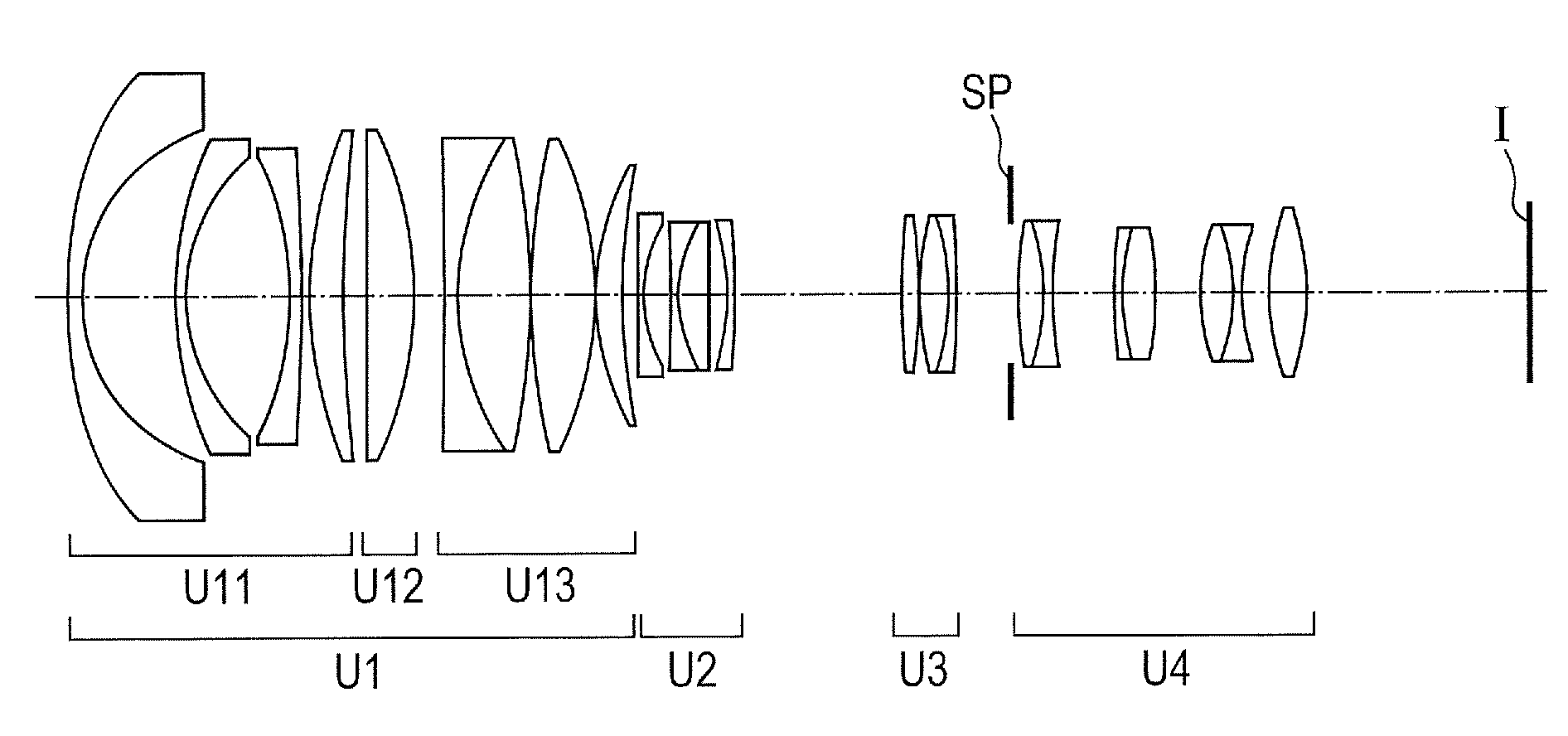
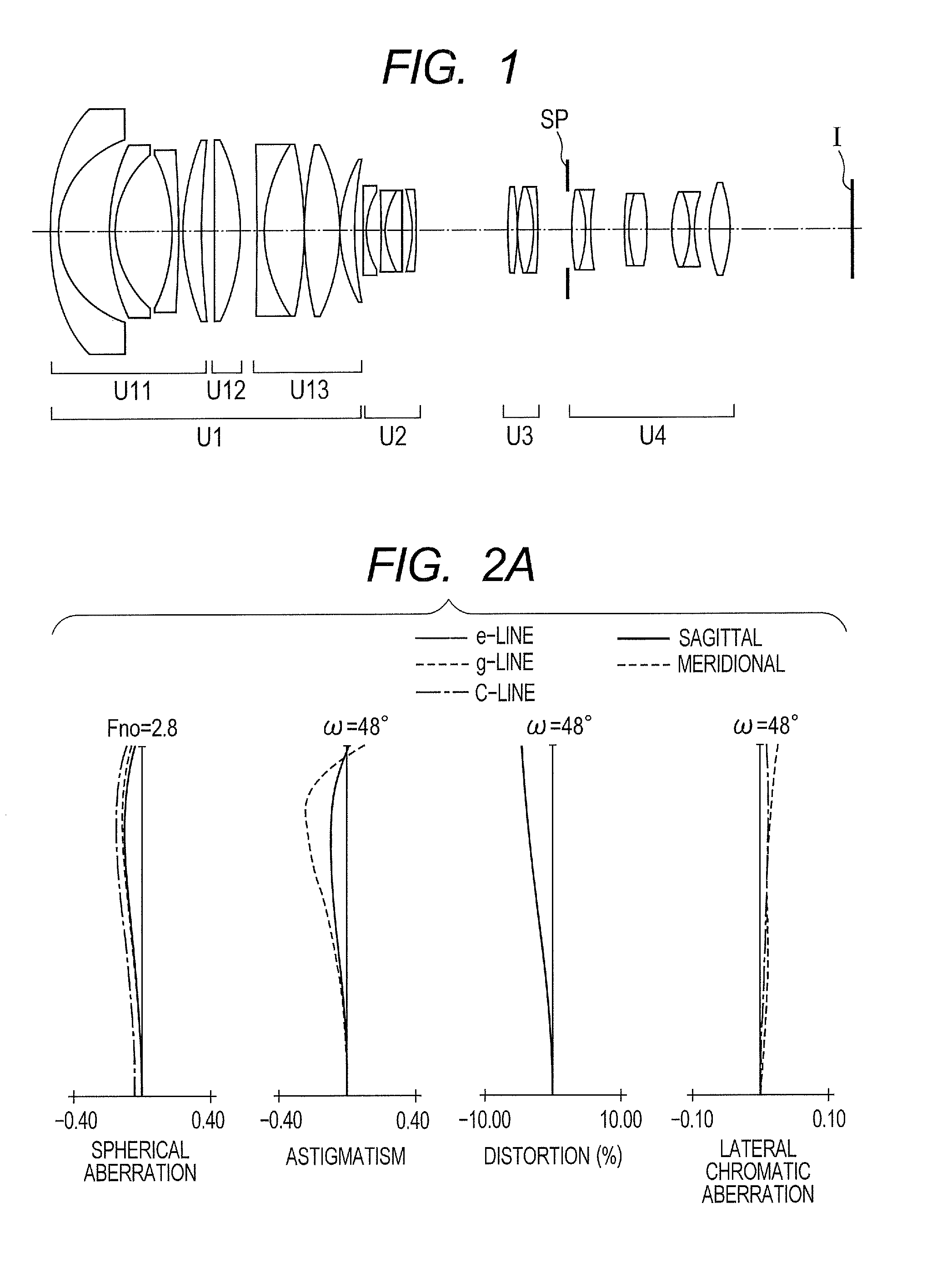
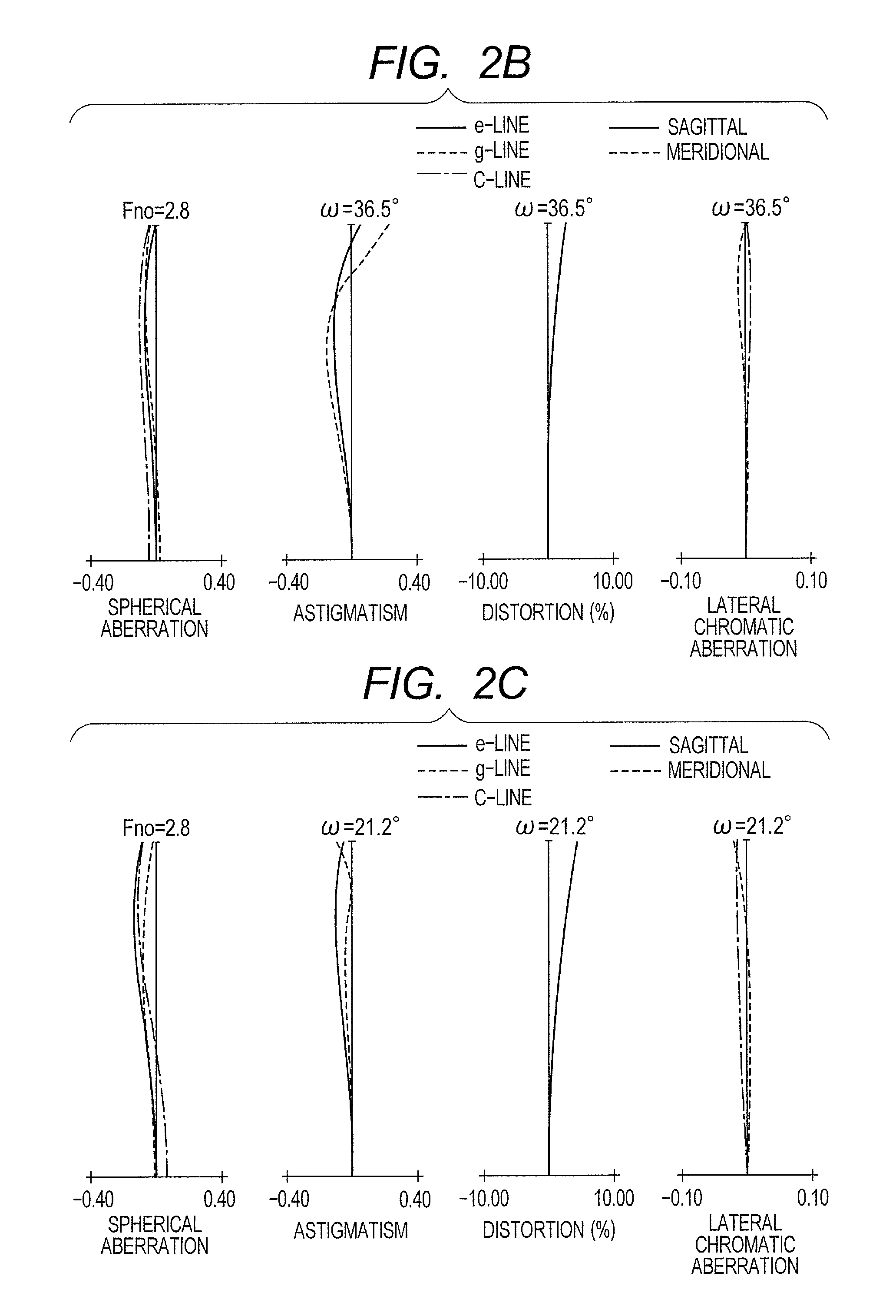
[0114]The specific lens configuration according to a first embodiment of the present invention will be described below with reference to FIG. 1.

[0115]The zoom lens shown in the first embodiment includes, in order from the object side: a first lens unit having positive refractive power, which does not move for varying magnification; a second lens unit having negative refractive power, which moves during varying magnification; a third lens unit having positive refractive power, which plays a role of correcting an image plane variation during varying magnification; and a fourth lens unit having positive refractive power, which does not move for varying magnification.

[0116]The first lens unit includes, in order from the object side, a first lens subunit having negative refractive power, which does not move for focusing, a second lens subunit having positive refractive power, which moves in the optical axis direction during focusing, and a third lens subunit having positive refractive po...

embodiment 2

[0121]The specific lens configuration according to a second embodiment of the present invention will be described below with reference to FIG. 3. In the each of the following embodiments, a difference between each embodiment and the previously described embodiment, and a feature of each embodiment will be mainly described.

[0122]The zoom lens shown in the second embodiment includes a first lens subunit which includes, in order from the object side, two lenses having negative refractive power and one lens having positive refractive power. A space between the lenses is appropriately secured, and thereby the first lens subunit attains the further reduction in the size and weight and an adequate optical performance at the same time, without extremely enhancing the refractive power of the lenses. Furthermore, an aspherical surface is arranged on the first lens having negative refractive power in the first lens subunit, and thereby the aberrations, in particular, a field curvature and a di...

embodiment 3

[0124]The specific lens configuration according to a third embodiment of the present invention will be described below with reference to FIG. 5.

[0125]In the zoom lens shown in the third embodiment, an aspherical surface is arranged on the first lens having negative refractive power in a first lens subunit, and an aspherical surface is arranged on a lens having a positive refractive power in a second lens subunit. Thereby, the zoom lens corrects the aberration in a wide angle side, and effectively corrects a field curvature, a distortion and the like in particular. A second lens unit includes, in order from an object side, two lenses having negative refractive power, and a cemented lens constituted by a negative lens and a positive lens. The second lens unit arranges a negative lens in the side close to the object, and thereby strengthens an action of positioning the object side principal point of the second lens unit to the object side, which is advantageous to the widening of the a...


PUM


Abstract

A zoom lens includes, in order from an object side to an image side: a positive first lens unit; a negative second lens unit; a positive third lens unit; and a positive fourth lens unit, wherein the first lens unit includes a positive first lens subunit, which does not move for focusing, a positive second lens subunit, which moves during the focus adjustment, and a positive third lens subunit, which does not move for focusing; and focal lengths of the first lens unit, the second lens unit, the third lens unit, a magnification of the third lens unit U3 at a wide angle end, focal lengths of the first lens subunit, the second lens subunit appropriately satisfy certain relations.

Description

BACKGROUND OF THE INVENTION[0001]1. Field of the Invention[0002]The present invention relates to a zoom lens and an image pickup apparatus having the same, and particularly relates to a broadcasting television camera, a cinema camera, a video camera, a digital still camera, a silver halide film camera and the like.[0003]2. Description of the Related Art[0004]An image pickup apparatus such as a broadcasting television camera, a cinema camera, a silver halide film camera, a digital camera and a video camera has been conventionally desired to be provided with a zoom lens which has a reduced size and weight, a high zoom ratio, and besides, an adequate optical performance. Particularly, an imaging device such as CCD and CMOS which are used in a television / cinema camera of a moving image photographing system for professionals has an almost uniform resolving power over the whole imaging range. Because of this, the zoom lens to be used in this system is required to have an almost uniform re...

Claims


Application Information

Patent Timeline
Patent Type & Authority Patents(United States)
IPC IPC(8): G02B15/14
CPCG02B15/14G02B15/173G02B15/144113
Inventor HORI, MASAO
Owner CANON KK
Why Eureka
Try Eureka