Method and system for tissue imaging and analysis

a tissue imaging and analysis technology, applied in the field of backscatter waveform measurement, can solve the problems of reducing the capacity of this technology to enable continued imaging, affecting the patient and physician, and limiting the identification of desirable tissue, so as to achieve high resolution, accuracy, and precision

Inactive Publication Date: 2014-11-11
PERSEUS BIOMED
View PDF28 Cites 2 Cited by
  • Summary
  • Abstract
  • Description
  • Claims
  • Application Information

AI Technical Summary

Benefits of technology

[0028]There is thus a need for, and it would be highly advantageous to have a method, and corresponding device and system thereof, using ultrasonic differential backscatter analysis of ultrasound excited tissue in time, for mapping and / or identification of tissue to types or substance composition. Moreover, there is a need for such an invention which achieves high resolution, accuracy, and precision.
[0037]The present invention is generally applicable for imaging of the examined area, for identifying tissue irregularities and / or the identification of tissue material or suspected material type in the examined locations. The present invention provides an accurate and precise tissue inspection procedure. The present invention is generally applicable for identifying a biopsy location to verify biopsy sample is drawn from the location of suspected malignancy / illness area; and / or identify the type of tissue in the suspected area for its illness type; and / or indicate the likelihood of the sampled area as of being with one or more characteristics / malignancy / illness. The present invention may be usable in determining glucose level in the blood and / or determining the likelihood of this level being below a normal level, or being above a certain level. The present invention is relatively inexpensive to construct and implement, and is especially suitable for application in hospital equipment, medical lab equipment, medical point of care, and private medical use.
[0039]According to another aspect of the present invention there is provided a device for differential excitation of tissues, herein, also referred to as the ultrasonic limited excitation device, that excites the diagnosed area in energy levels adequate for overcoming the natural balancing systems of the body, so as to create gradients in the scattering behavior of tissues in the examined area across more than 1% of each second, and / or for more than 200 milliseconds. The device is limited in the energy levels it transmits to the patient such that will not cause any harm or therapeutic effects, and hence is limited in not heating any portion of the examined area with more than a preset of 1 degree Celsius from its original temperature.
[0047]As will be described more particularly below, the invention enables attaining one or more of the following advantages.
[0048]1. The use of an Ultrasound excited backscatter system enables accurate localization of a biopsy needle at the location of suspected malignant tissue, such that the sample is taken from an irregular substance within the organ.
[0050]3. The use of an Ultrasound excited backscatter system enables accurate localization of a brachytherapy needle at the location's of suspected malignant tissue, such that radioactive substance is placed at the suspected malignant tissue.

Problems solved by technology

X-Ray based tomography uses high energy electromagnetic radiation that is harmful to both patient and physician.
This harmful effect substantially reduces the capacity of this technology to enable continues imagery.
As X-Ray technology mainly measures acid levels in the examined area, it is limited to identifying desirable tissue differences where acid levels substantially differ.
As such it yields very high cost of ownership.
The need for very accurate magnetic field in MRI equipment substantially limits the geometry of the equipment, not enabling desirable physician interaction with the body of the patient at affordable costs.
PET technology is limited in its capacity to identify desirable substance composition differences, and hence is used mainly in conjunction with other imaging techniques.
Ultrasound-diagnostics equipment mostly analyzes ultrasound waves' specular reflection; as such it is limited in its capacity to identify desirable tissue substance as sonic echo does not differentiate well enough between tissue materials.
Advanced ultrasound techniques use other characteristics of the echo reflectance in the body, such as ultrasonic backscatter of power waves for elasticity measurement, however those too are not sufficient for clear differentiation between different tissue types or substances in the examined organs.
However, the technique could still be used to measure a relative temperature response, even if the temperature dependence of sound speed and the thermal expansion coefficient of the tissue are not known very accurately.
IR imagery is used to map the tissue's natural heat superficially, however due to the mammal natural heat control mechanisms, temperature is equalized by in-vivo tissues as heat conduction and convection occur within the organ, hence this technology is very limited in its capacity to identify desirable tissue substance.
The limitation of such technologies is in the need to sample out tissue from the organs, sometimes without knowing whether the sample is taken from the correct position inside the organ.
Other limitations are the required handling, and the fact it is analyzed out of the living organ after loosing some of its characteristics.
These currently available techniques from the prior art hence enable less than desirable functionality of real time imaging / identification or differentiation of in-vivo tissue.
Blood sampling techniques known form the prior art are based on drawing of blood from the body and lack the ability of identifying the point in time where glucose levels non-linearly change from acceptable levels.
The motion of the tissue in the ultrasound fields causes motion artifacts which affect the contrast of the MR image.

Method used


Image

  • Method and system for tissue imaging and analysis
  • Method and system for tissue imaging and analysis
  • Method and system for tissue imaging and analysis

Examples


Embodiment Construction

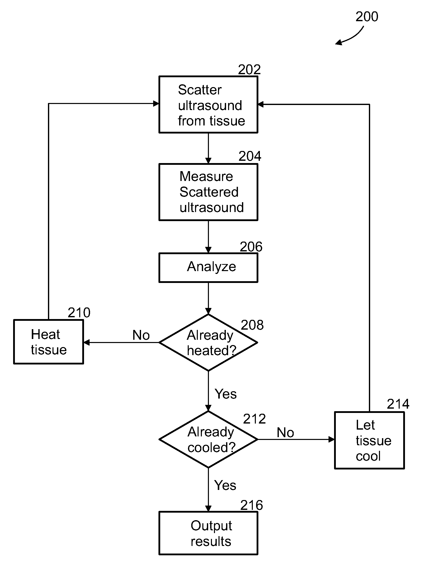
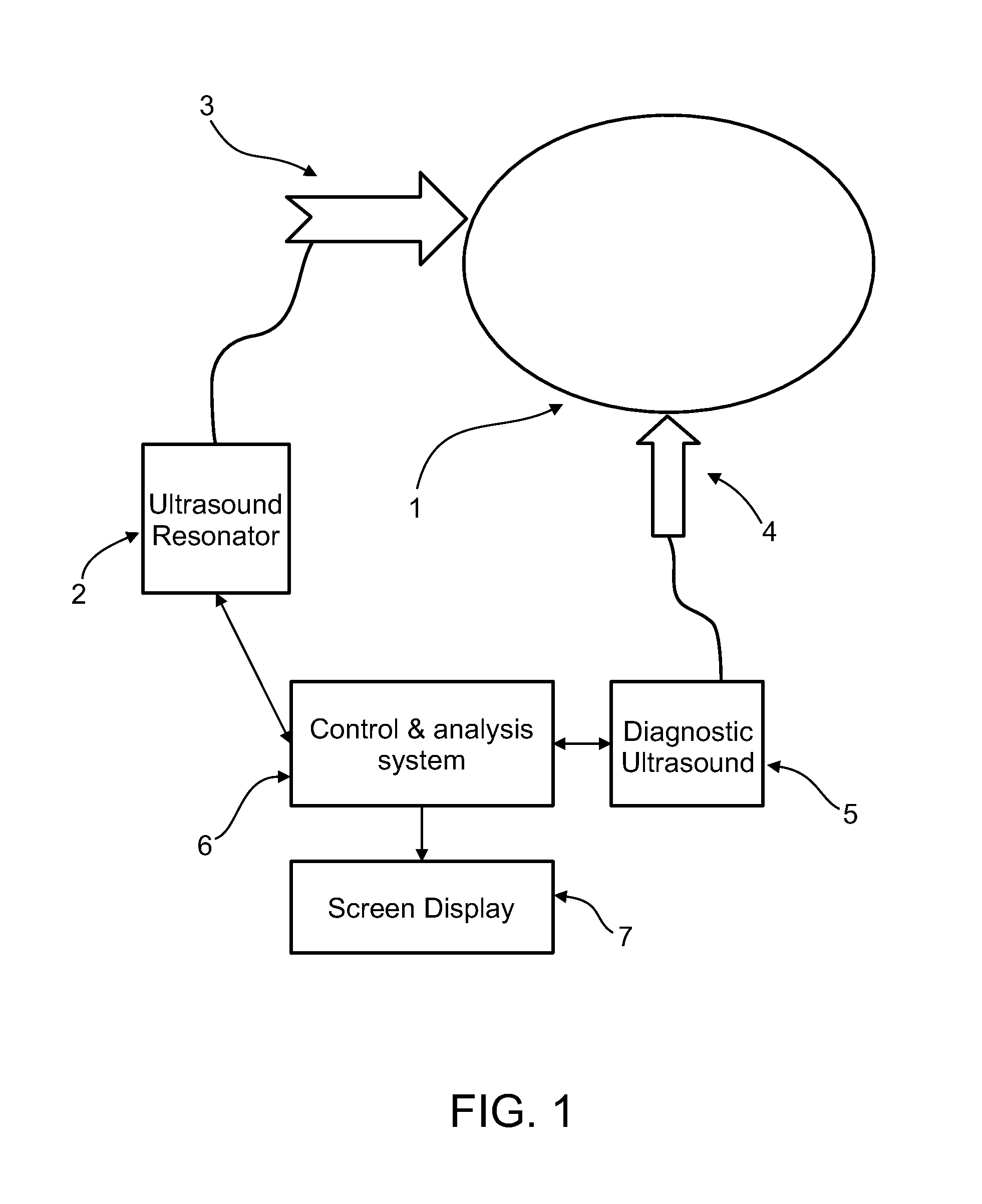
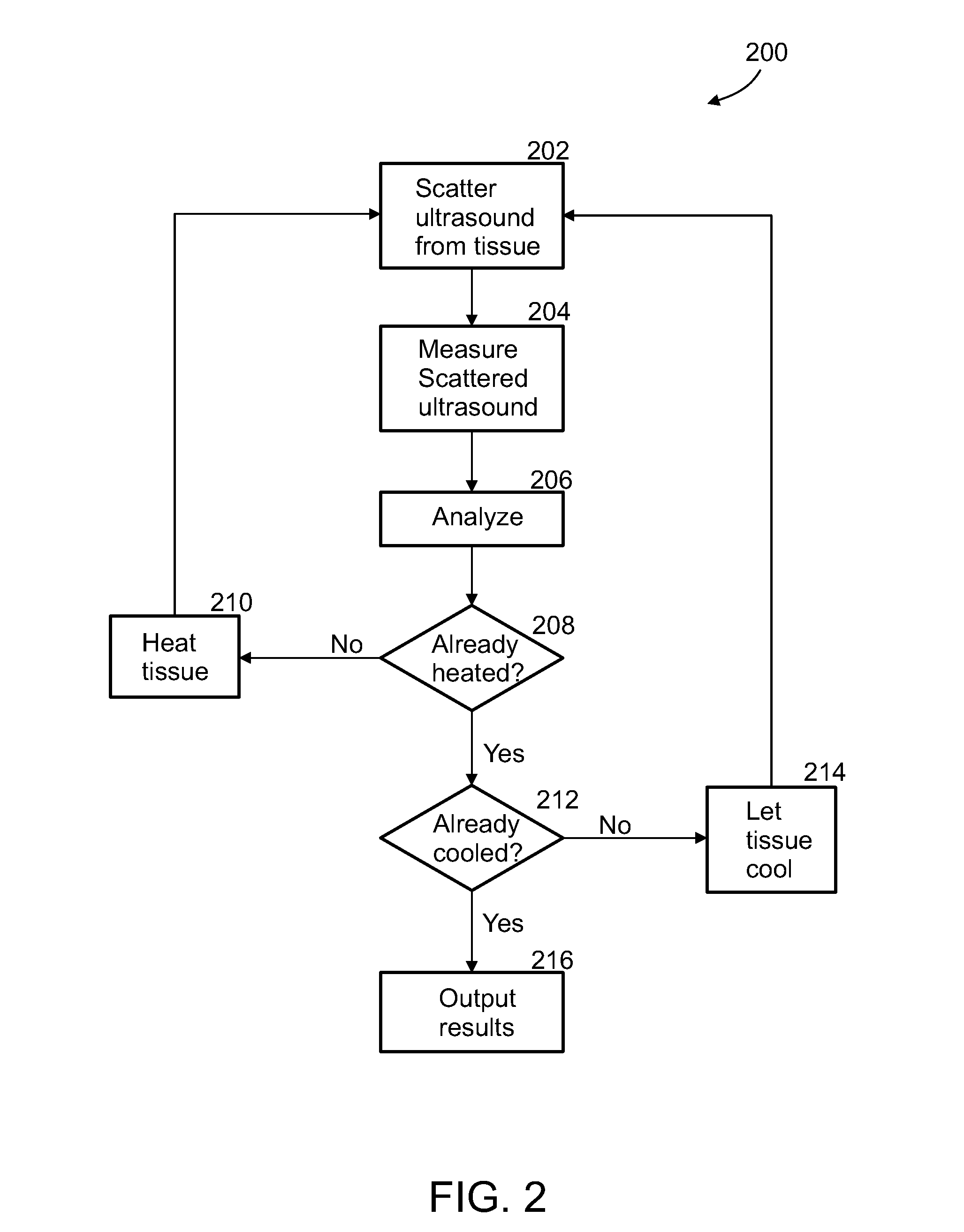
[0089]An aspect of some embodiments of the invention concerns a method and system for the imaging or identification of tissue type or substance and / or irregularities based on its behavior under ultrasonic heating over time. The system includes an ultrasound resonator for differential heating of different types of tissue, and the same or another ultrasonic device or machine measuring changes in ultrasonic backscatter over time, as a result of tissue heating. In addition, the system includes computer algorithms analyzing ultrasonic backscatter patterns and gradients, as a result of the heating in the examined area over time and location to image the internal subregions of tissues in the examined area. The system is built from single / multiple ultrasonic frequency transmitters, transmitting ultrasonic waves at certain frequency or frequencies, certain amplitude / amplitudes and energy levels. The exposed area is heated; it absorbs some of the ultrasonic energy, and as a result, changes it...


PUM


Abstract

A method for detecting abnormal tissue in a region of healthy tissue, comprising:a) making a first measurement of ultrasound backscattered from the region;b) heating the region, at least after the first measurement;c) making one or more additional measurements of ultrasound backscattered from the region after some or all of the heating; andd) analyzing the measurements to detect the abnormal tissue by finding one or both of differences in changes in temperature and differences in thermal expansion, caused by the heating, between the abnormal tissue and the healthy tissue.

Description

RELATED APPLICATIONS[0001]This application is a National Phase of PCT Patent Application No. PCT / IB2010 / 056117 having International filing date of Dec. 29, 2010, which is a continuation-in-part (CIP) of U.S. patent application Ser. Nos. 12 / 648,440 and 12 / 648,433, both filed on Dec. 29, 2009. U.S. patent application Ser. No. 12 / 648,440 claims the benefit of priority under 35 U.S.C. §119(e) from U.S. Provisional Patent Application No. 61 / 193,829 filed on Dec. 29, 2008, . U.S. patent application Ser. No. 12 / 648,433 claims the benefit of priority under 35 U.S.C. §119(e) from U.S. Provisional Patent Application Nos. 61 / 182,781 filed on Jun. 1, 2009, and 61 / 193,815 filed on Dec. 29, 2008. The contents of all the above application are incorporated herein by reference as if fully set forth herein.[0002]PCT Patent Application No. PCT / IB2010 / 056117 is also related to PCT Patent Application No. PCT / IB2010 / 056116 filed on Dec. 29, 2010, the contents of which are incorporated herein by reference...

Claims


Application Information

Patent Timeline
Patent Type & Authority Patents(United States)
IPC IPC(8): A61N7/02A61B5/01A61B10/02A61B5/145A61B8/00A61B8/08
CPCA61B5/14532A61B10/0233A61B8/085A61B8/48A61B8/0841A61B5/015A61N7/02
Inventor BEHAR, BOAZ
Owner PERSEUS BIOMED
Why Eureka
Try Eureka