Method for plant monitoring with a field bus of process automation technology

a technology of process automation and field bus, applied in the direction of program control, total factory control, instruments, etc., can solve the problems of long reaction time, long reaction time, and inconvenient monitoring of plant monitoring, so as to achieve the highest degree of independen

Active Publication Date: 2014-11-11
ENDRESSHAUSER PROCESS SOLUTIONS
View PDF18 Cites 9 Cited by
  • Summary
  • Abstract
  • Description
  • Claims
  • Application Information

AI Technical Summary

Benefits of technology

[0021]An object of the invention is to provide a method for plant monitoring with a fieldbus of process automation technology not having the above discussed advantages, while possessing a highest possible measure of independence from the process control and, in spite of this, reacting to diagnostic events as quickly as possible.
[0022]This object is achieved by a method comprising the steps of: monitoring by a plant monitoring unit regular, process-control, data traffic carried on a fieldbus to which a plurality of field devices are connected; examining telegrams of the regular data traffic for information indicating a diagnostic event at one of the field device; and, in case of a telegram with an indication of a diagnostic event being detected, requesting by the plant monitoring unit further diagnostic information from such field device.

Problems solved by technology

Especially in the case of plants having a significant number of installed field devices and a multiplicity of diagnostically relevant parameters to be monitored, it is a fact that the updating of these parameters in the asset-management-system takes a very long time, so that long reaction times result.
These long reaction times are very disadvantageous, especially in the case of critical diagnostic events.
The long reaction times can even compromise the ability of the asset management systems to function.

Method used


Image

  • Method for plant monitoring with a field bus of process automation technology
  • Method for plant monitoring with a field bus of process automation technology
  • Method for plant monitoring with a field bus of process automation technology

Examples


Embodiment Construction

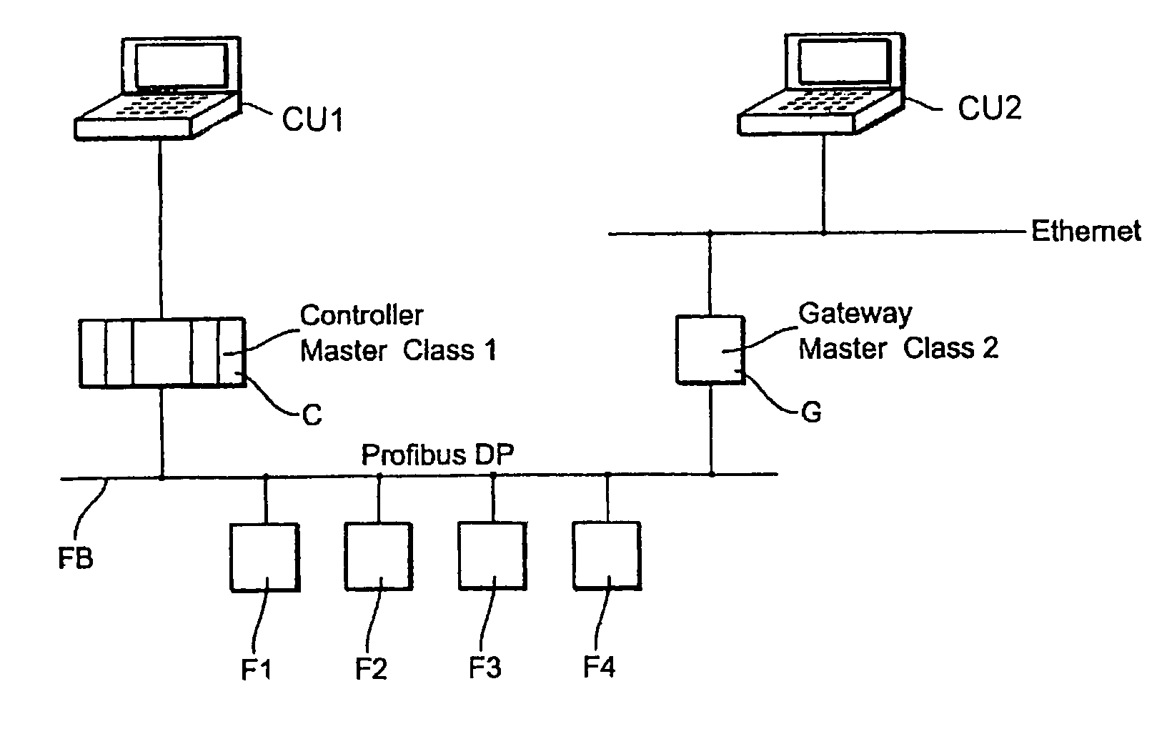
[0026]FIG. 1 shows a network of process automation technology. Attached to a fieldbus FB are a plurality of field devices F1, F2, F3 and F4. Additionally connected to the fieldbus FB are a controller C (for example, FieldController of the firm, Endress+Hauser) and a gateway G (for example, FieldGate of the firm, Endress+Hauser). Controller C is connected with a computer unit CU1 serving as a visualizing system. Gateway G is connected with a computer unit CU2, which serves for observing field devices.

[0027]Field devices F1 to F4 are configured as slaves. Controller C is configured as Master Class 1 and Gateway G as Master Class 2. Serving as process control unit is controller C, which cyclically sends output data to the individual field devices and receives output data from the individual field devices.

[0028]Serving as plant monitoring unit is the Gateway G, which communicates acyclically with the field devices.

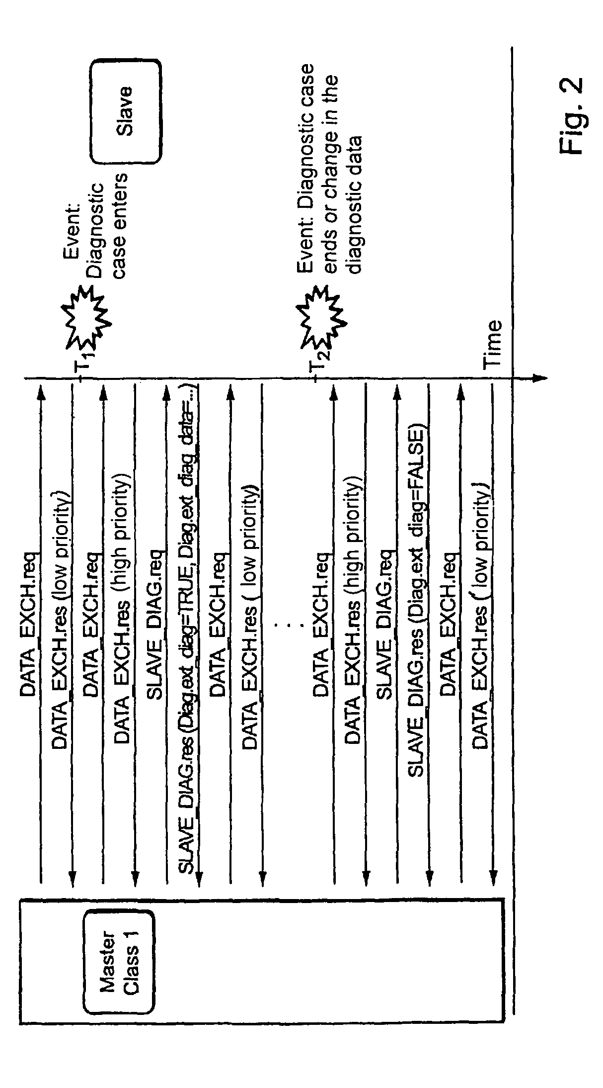
[0029]FIG. 2 shows, schematically, a timing diagram for communication bet...


PUM


Abstract

A method for plant monitoring with a fieldbus of process automation technology, wherein a plurality of field devices communicate with a process control unit and a plant monitoring unit The method steps are carried out as follows: the regular, process-control, data traffic on the fieldbus is monitored by the plant monitoring unit; an examination of the telegrams of the regular data traffic for information indicating a diagnostic event at one of the field devices is performed; and in case a telegram is detected having an indication of a diagnostic event, the plant monitoring unit requests further diagnostic information from the pertinent field device.

Description

TECHNICAL FIELD[0001]The invention relates to a method for plant, or installation, monitoring with a field bus of process automation technology, as such method is defined in the preamble of claim 1.BACKGROUND DISCUSSION[0002]In automation technology, field devices are often used, to serve for measuring and / or influencing process variables. Examples of such field devices are fill-level measuring devices, mass-flow measuring devices, pressure and temperature measuring devices, etc., which, as sensors, register the corresponding process variables, fill-level, flow (e.g. flow rate), pressure and temperature.[0003]Field devices serving as actuators, to influence process variables, include, e.g., valves for controlling flow of a liquid in a section of pipeline or pumps for controlling fill level in a container.[0004]A large number of such field devices are manufactured and sold by the firm, Endress+Hauser.[0005]As a rule, field devices in modern manufacturing plants are connected via comm...

Claims


Application Information

Patent Timeline
Patent Type & Authority Patents(United States)
IPC IPC(8): G06F15/16G05B19/418G06F15/173G05B9/02
CPCG05B2219/31211G05B19/4184G05B2219/33209G05B2219/31121Y02P90/02
Inventor HAHNICHE, JORGROMER, MATTHIAS
Owner ENDRESSHAUSER PROCESS SOLUTIONS
Why Eureka
Try Eureka