
Bicycle seat tube

a seat tube and bicycle technology, applied in the field of seat tubes, can solve the problems of affecting the performance of the bicycle, and affecting the stability of the bicycle, so as to reduce the transmission of vibrations

Active Publication Date: 2014-11-18
SPECIALIZED BICYCLE COMPONENTS INC
View PDF119 Cites 74 Cited by
  • Summary
  • Abstract
  • Description
  • Claims
  • Application Information

AI Technical Summary

Benefits of technology

[0009]Accordingly, a need exists for a cost-effective method of reducing vibrations from being transmitted from the wheels of a bicycle to the rider of the bicycle. Some embodiments of a seat tube assembly include a cavity between the walls of the seat tube assembly and the seat post. The seat post assembly can also include a vibration damping member. Preferably, the vibration damping member is constructed from an elastomeric material. The seat tube assembly can be constructed from a carbon fiber material and / or a metal material, such as steel, aluminum, and titanium.
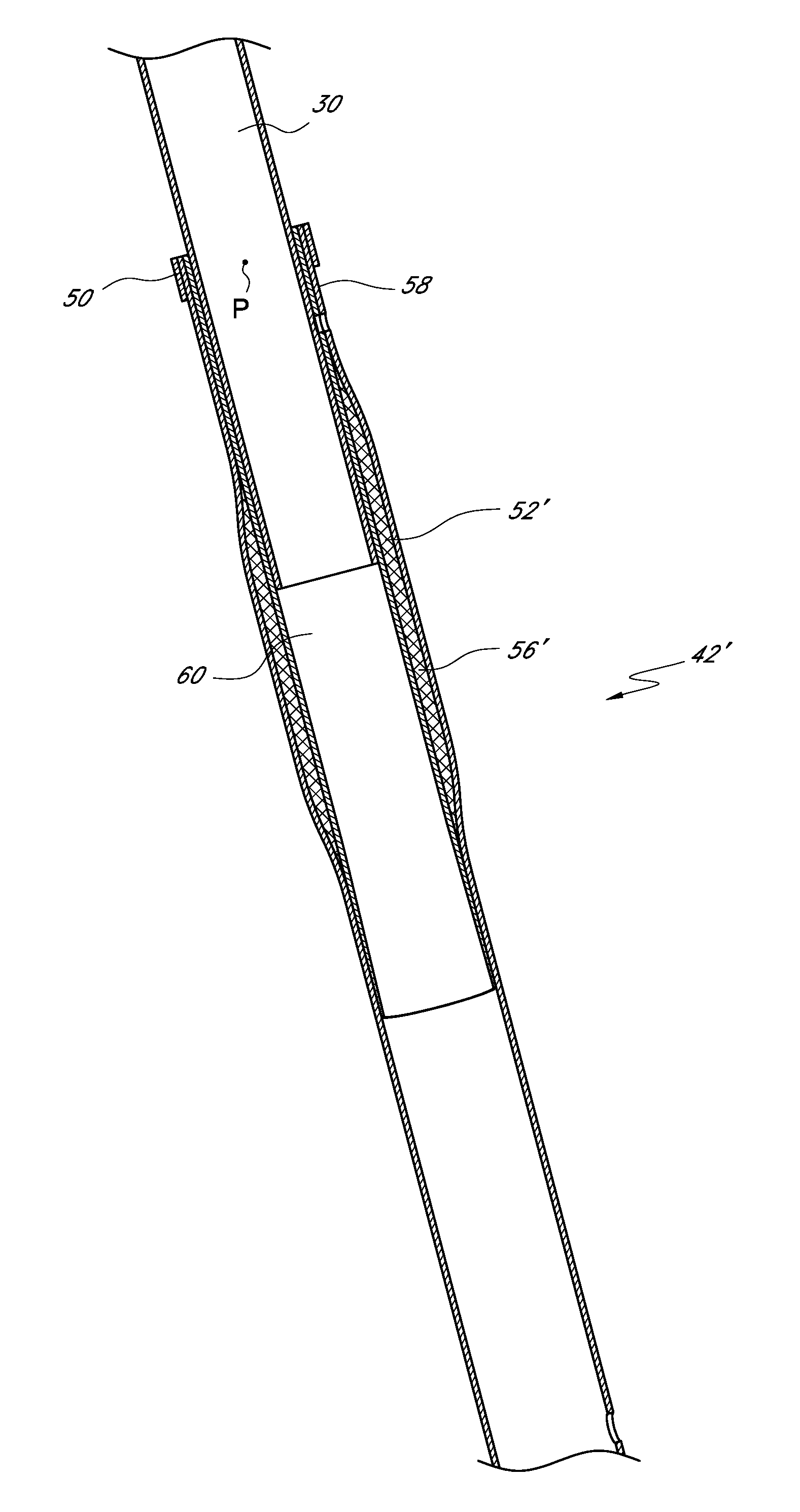
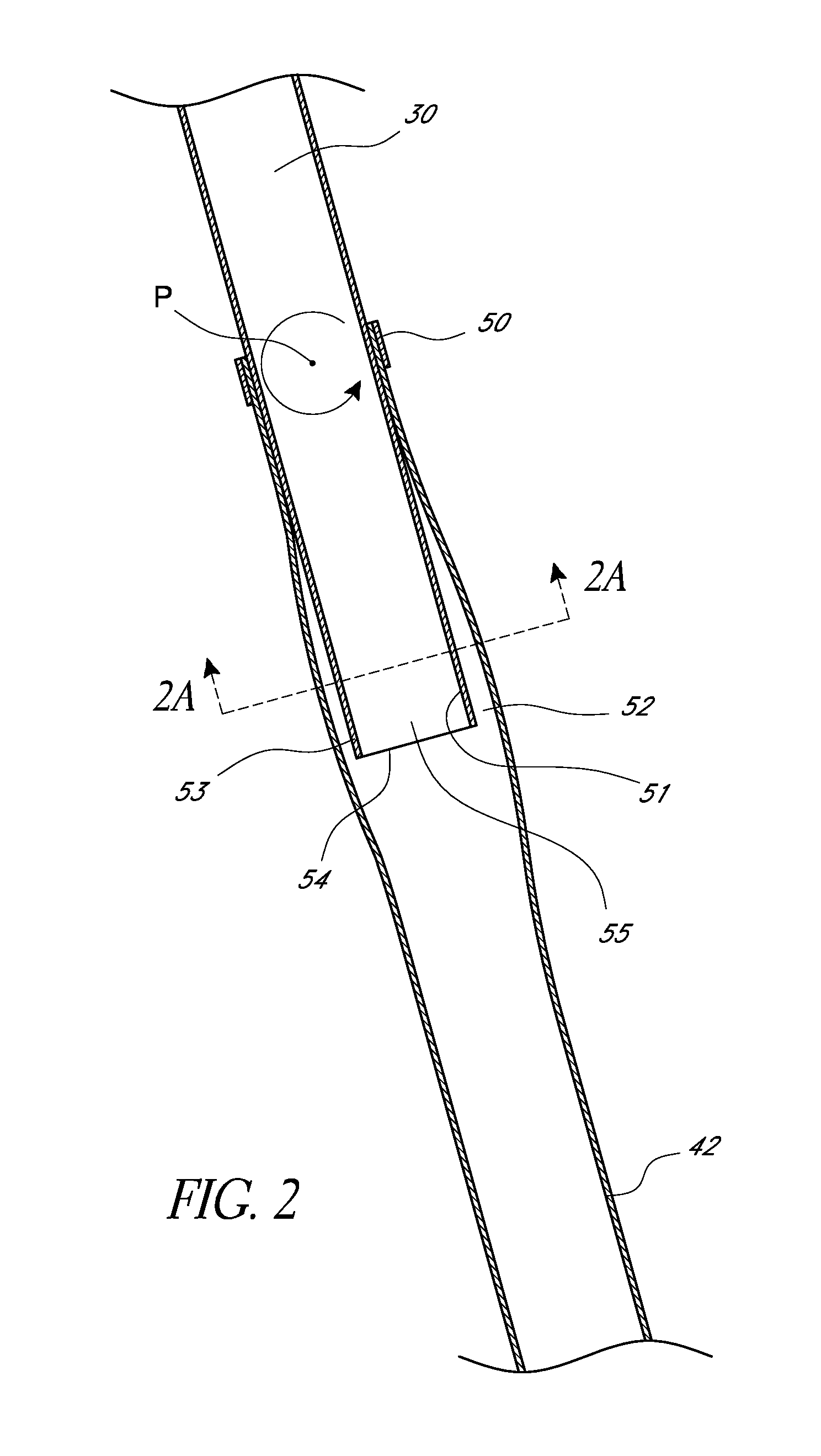
[0010]In some embodiments, a bicycle can have a main frame with a top tube, a head tube, a down tube, and a seat tube. The bicycle may also include a seat post having first and second ends, the first end configured to connect to a saddle and the second end configured for insertion into the seat tube. A clamp can secure the seat post to the seat tube. The seat tube can include an open cavity where the open cavity defines a space between an outer wall of the seat post and an inner wall of the seat tube. The outer wall can be substantially parallel to the inner wall. The seat tube can be configured to allow the seat post to rotate about the clamp to thereby decrease vibrations transmitted to a rider of the bicycle.
[0012]Some embodiments can include a bicycle frameset or a bicycle module that can include a top tube, a down tube, a head tube connected to the top tube and the down tube and a seat tube connected to the top tube and the down tube. They may further include a fork assembly configured for insertion into the head tube and a seat post configured to connect to a saddle at a first end and a second end configured for insertion into the seat tube. A clamp can secure the seat post within the seat tube. The seat tube can be configured to secure said seat post substantially only at the clamp so that the seat post is able to rotate about the clamping location within a space between the seat post and the seat tube and within the seat tube. In some embodiments, there may be a damping member within the seat tube and between the seat tube and the seat post.

Problems solved by technology

Bicycle riding and racing often takes place on less than ideal terrain conditions.
In more populated areas, a significant portion of paved roads may be damaged and in need of repair.
When traversed by the bicycle, these irregular surfaces transmit vibrations to the bicycle.
Furthermore, the surface of even relatively new pavement, while acceptable for motor vehicles, may be rough enough to transmit significant vibration to a bicycle.
When transmitted to the rider, these vibrations often cause discomfort and fatigue.
Although highly favored in some applications, such as bicycles intended primarily for off-road use, such suspension assemblies have generally been unsuccessful in connection with bicycles primarily intended for use on paved surfaces (i.e., road bicycles), where low weight and aerodynamics are considered highly important.
Furthermore, such suspension assemblies are intended to absorb large bumps and may not be effective at isolating vibrations due to inherent friction within the assembly, which may prevent movement of the suspension assembly in response to small forces.
However, although carbon fiber is lightweight and exhibits improved vibration damping characteristics in comparison to metal, a significant amount of vibration may nonetheless be transferred through components made from carbon fiber.

Method used


Image

  • Bicycle seat tube
  • Bicycle seat tube
  • Bicycle seat tube

Examples


Embodiment Construction

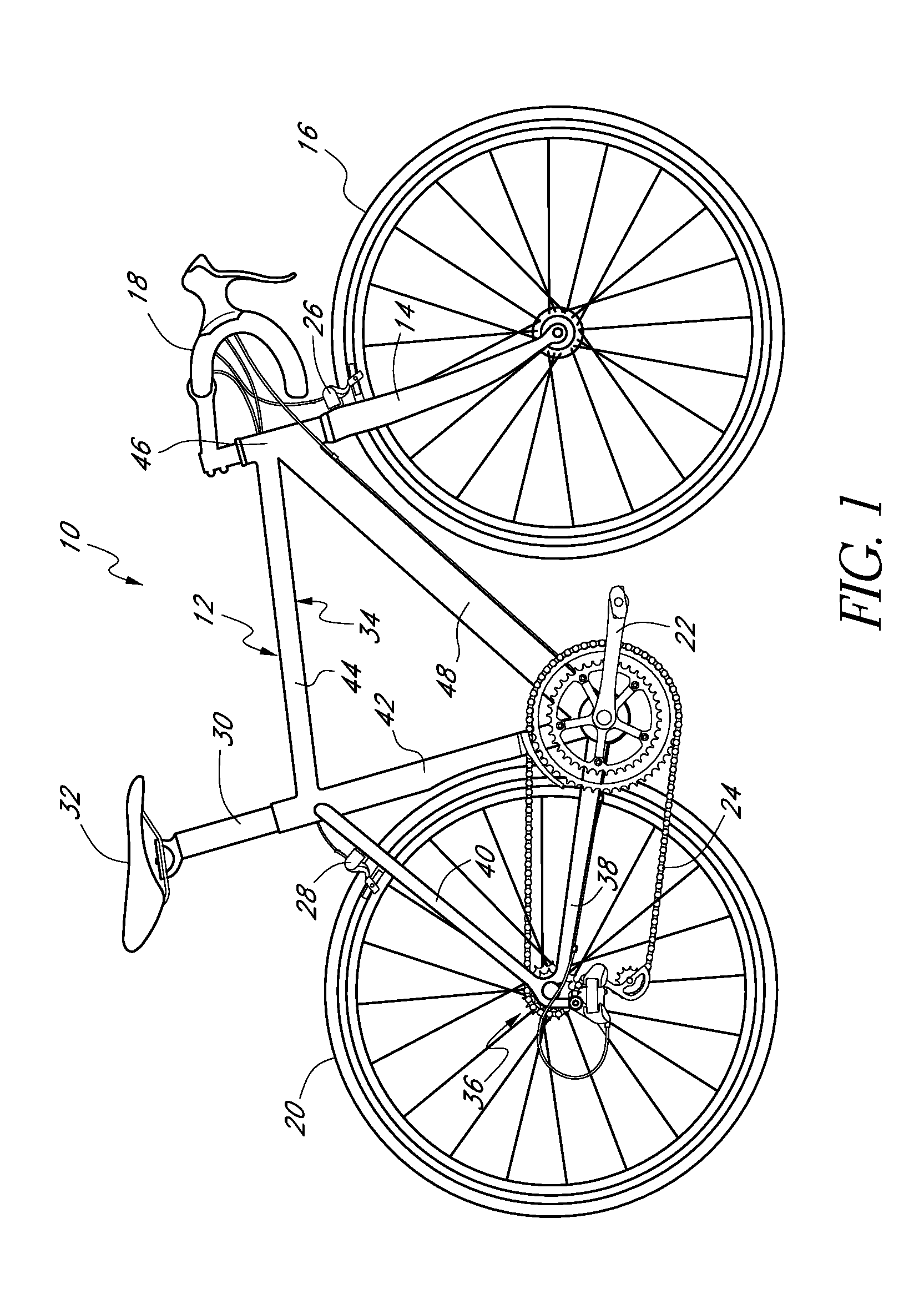
[0022]FIG. 1 illustrates a bicycle, which is referred to generally by the reference numeral 10. The bicycle 10 includes a frame 12, which rotatably supports a wheel support, or front fork assembly 14, near a forward end of the frame 12 for rotation about a steering axis. A lower end of the fork assembly 14 supports a front wheel 16 of the bicycle 10. A handlebar assembly 18 is connected to an upper end of the fork 14 for rotating the fork assembly 14 and front wheel 16 about the steering axis of the bicycle 10. In addition, the handlebar assembly 18 may include one or more rider controls, such as shifting or braking controls.

[0023]A rear wheel 20 of the bicycle 10 is supported near a rearward end of the frame 12. A pedal crank assembly 22 is rotatably supported by a lower portion of the frame 12. A drive chain 24 extends between the pedal crank assembly and the rear wheel to transfer power therebetween, as is well known in the art.

[0024]A front brake caliper 26 can be supported by t...


PUM


Abstract

A bicycle seat tube assembly and seat post can be arranged to reduce vibrations that originate at the bicycle wheel and are transmitted to the rider of the bicycle. Desirably, a saddle is configured to be supported by a seat post which connects to a bicycle frame at the seat tube assembly. An open cavity can be formed between the seat tube assembly and the seat post. The open cavity can be configured to allow the system to act as a spring. Further, spring stiffness can be adjusted to reduce vibrations and increase damping.

Description

CROSS-REFERENCE TO RELATED APPLICATIONS[0001]This application claims the benefit under 35 U.S.C. §119(e) of U.S. Provisional Application No. 61 / 321,796 filed Apr. 7, 2010, titled BICYCLE SEAT TUBE, the entire contents of which is hereby incorporated by reference herein and made a part of this specification.BACKGROUND OF THE INVENTION[0002]1. Field of the Invention[0003]The present invention generally relates to bicycles. More particularly, the present invention relates to a seat tube configured to reduce vibrations transmitted to a rider of the bicycle.[0004]2. Description of the Related Art[0005]Bicycle riding and racing often takes place on less than ideal terrain conditions. For example, bicycle touring and racing may often take place on country roads, which may be unpaved or where the pavement may be rough and irregular, even when new. In more populated areas, a significant portion of paved roads may be damaged and in need of repair. When traversed by the bicycle, these irregula...

Claims


Application Information

Patent Timeline
Patent Type & Authority Patents(United States)
IPC IPC(8): B62J1/02B62K19/36
CPCB62K2201/02B62K19/36B62J1/02
Inventor CHUBBUCK, KYLE, L.
Owner SPECIALIZED BICYCLE COMPONENTS INC
Learn More