Segmented deployable boom structure for space applications

a space application and boom technology, applied in the field of deployable space structures and booms, can solve the problems of limiting the capability of spacecraft, insufficient boom technology for meeting emerging applications, and current boom assemblies that cannot be scalable to very long lengths, so as to reduce program delays and costs, the effect of unlimited structure scaling and shorter booms

Active Publication Date: 2014-11-25
DEPLOYABLE SPACE SYST
View PDF14 Cites 23 Cited by
  • Summary
  • Abstract
  • Description
  • Claims
  • Application Information

AI Technical Summary

Benefits of technology

[0009]The segmented boom elements are thin-walled composite reinforced, or metallic, elastically-deployable tubes with a longitudinal slit-opening down the entire backside of the segmented tube length. The slit-tube and thin-walled elastic nature of the segmented boom assembly allows it to be flattened, and then subsequently rolled up into an extremely compact cylindrical stowage volume.
[0019]3. The shaped ends may be tailored by the incorporation of a cut-out pattern to control the stiffness and parasitic mass.

Problems solved by technology

As increasingly advanced types of spacecraft are being developed, it has become apparent that currently boom technologies are insufficient for meeting emerging applications.
In particular, current boom assemblies are not scalable to very long lengths and this limits a spacecraft's capability, particularly for emerging missions that demand a much longer boom length to provide much higher power production from a solar array, or a much broader aperture for an antenna.
Continuous length booms of very long lengths are extremely difficult to manufacture using current state-of-the-practice technologies due to fabrication, material and facility limitations.
The articulated boom technology is high cost, high mass, and labor intensive to manufacture.

Method used


Image

  • Segmented deployable boom structure for space applications
  • Segmented deployable boom structure for space applications
  • Segmented deployable boom structure for space applications

Examples


Embodiment Construction

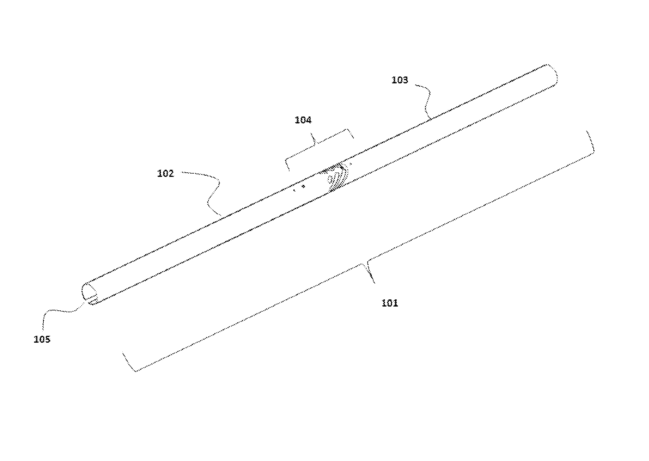
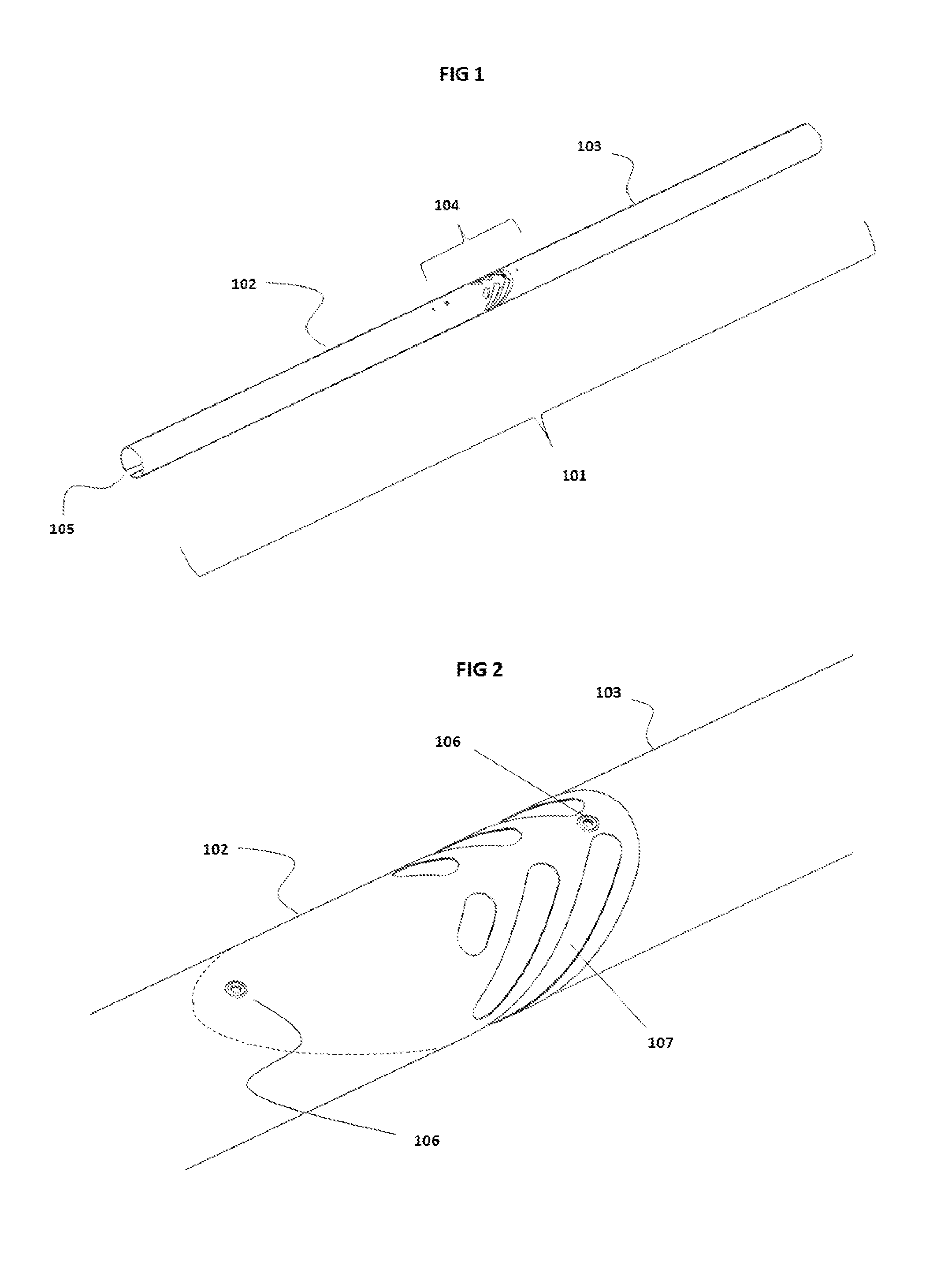
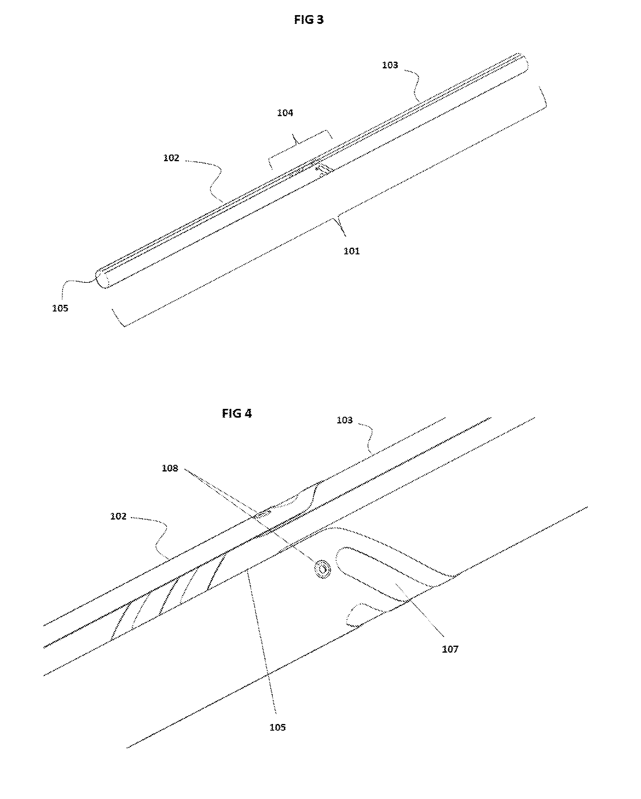
[0038]In the preferred embodiment, the segmented construction consists of multiple longitudinal and circumferential attachments within the overlapping splice region of the adjacent and contacting boom elements. Alternatively, attachments of the boom segments could occur through a continuous adhesive bond layer or discrete bonds. The combination of multiple longitudinal and circumferential attachments within the spliced region maintains the boom stiffness and minimizes the potential for local buckling within the region similar to a continuous co-cured boom. For mechanical attachments, the attachments at the overlapping splice region must be match drilled / located when the segmented booms are in the flattened state in order to allow for rolling / stowage. In the preferred embodiment the attachments are low profile fasteners, rivets, grommets, high-strength adhesive connections, or other. Mechanical attachments consisting of rivets, grommets or other low-profile-expandable fasteners maint...


PUM


Abstract

A long, elastically deployable tubular boom structure consisting of two or more thin-walled booms with a continuous longitudinal slit-opening along its entire length on the backside and a composite reinforced or metallic construction. The slit-opening, thin-walled tubular section accompanied by the boom elastic properties and unique fastening method between the boom segments allows the segmented boom to be flattened and then rolled up into an extremely compact cylindrical stowage volume. The boom elastically and immediately deploys from a rolled stowed configuration under its own strain energy without use of a motor or other complicated actuators / mechanisms. The segmented construction of multiple tube elements allows for unlimited boom lengths and enables unlimited structure scaling. In addition, the segmented slit-boom construction minimizes the overall boom cost and allows for tailoring of the boom stiffness along its length and facilitates repair of the boom if a material flaw is identified or localized damage occurs.

Description

FIELD OF THE INVENTION[0001]The present invention relates to deployable space structures and booms, and more particularly to the practical, affordable, modular, and segmented construction of extremely long length deployable structures and booms that also stow into a compact volume.BACKGROUND OF THE INVENTION[0002]Spacecraft systems, which include earth and planetary orbiting satellites and deep space probes, often incorporate deployable systems including; Deployable structures, deployable solar arrays, deployable antennas, and other deployable subsystems. These deployable systems must be configurable between a storage configuration that enables the entire spacecraft system, inclusive of the deployable structure, to fit within the small volume constraints of a launch vehicle, and a deployed operable configuration that enables the spacecraft to function in a desired manner once in space.[0003]Once the spacecraft is in space, the spacecraft is typically configured for use by deploying ...

Claims


Application Information

Patent Timeline
Patent Type & Authority Patents(United States)
IPC IPC(8): E04C3/00B64G1/22
CPCE04C3/00E04C3/005B64G1/22B64G1/222B64G1/44B64G1/66
Inventor SPENCE, BRIAN R.WHITE, STEVE F.DOUGLAS, MARK V.SCHMID, KEVIN B.CARTER, DONALD G. R.
Owner DEPLOYABLE SPACE SYST
Why Eureka
Try Eureka