
Compressor device

Active Publication Date: 2014-11-25
ATLAS COPCO AIRPOWER NV
View PDF21 Cites 0 Cited by
  • Summary
  • Abstract
  • Description
  • Claims
  • Application Information

AI Technical Summary

Benefits of technology

The invention is a device that automatically adjusts its compressor to prevent overheating and maintain good working condition even in high environmental temperatures. This is achieved through the monitoring of the temperature and the adjusting of the maximum allowed number of revolutions of the compressor. Additionally, the device can also include a cooling arrangement for the air that functions as a cooling medium for the electronic compartment, which can be switched on when the environmental temperature threatens to rise above a set level to keep energy costs low.

Problems solved by technology

In the case that the limits of the nominal environmental conditions are exceeded, then, the good working of the compressor device can no longer be guaranteed and that will lead to unpredictable stoppages of the compressor device.
This has the disadvantage that a bigger investment is necessary for the compressor device and that the compressor device is not optimally utilized under all nominal conditions with the result that there is a loss of performance in nominal conditions.

Method used


Image

  • Compressor device
  • Compressor device

Examples


Embodiment Construction

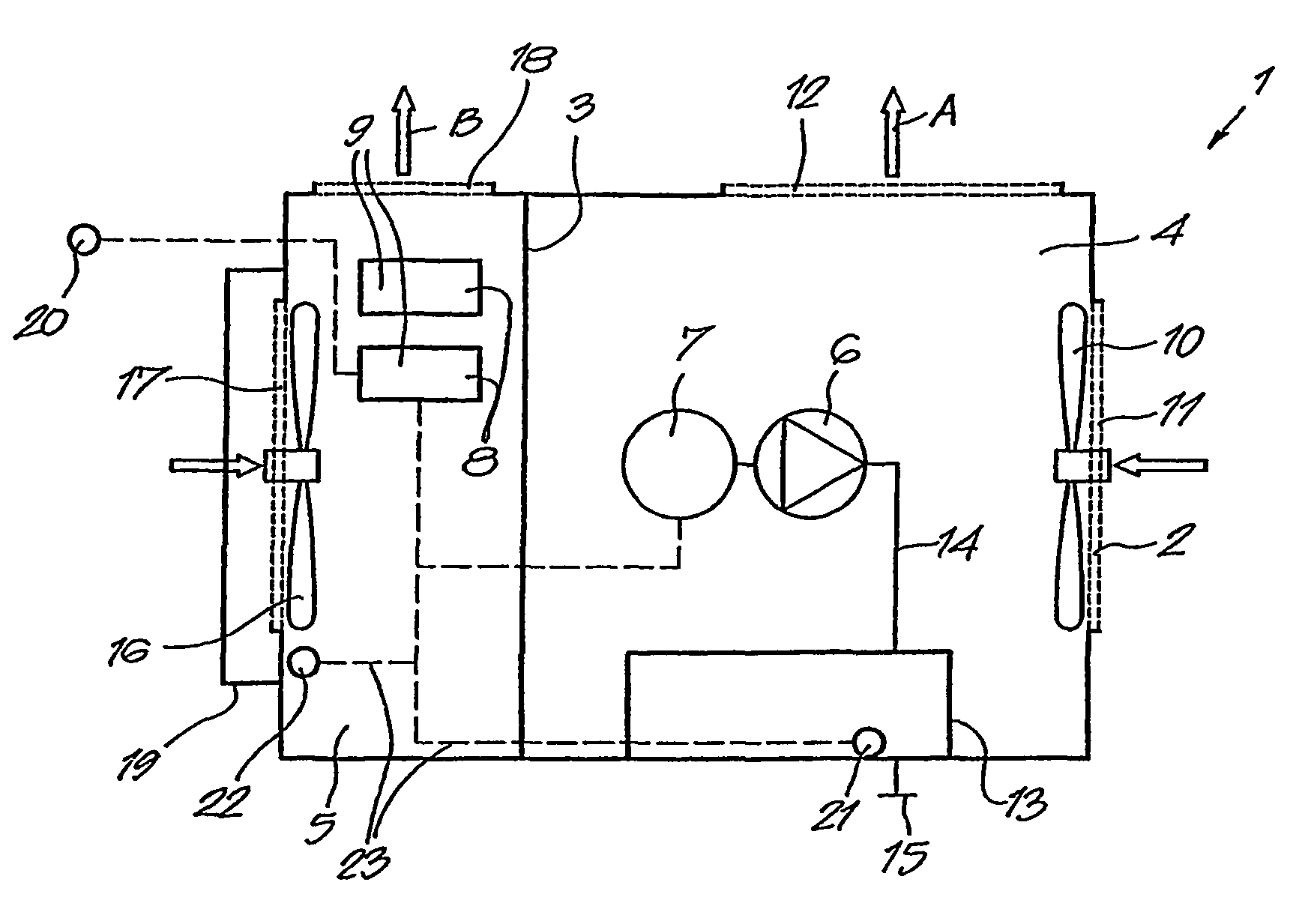
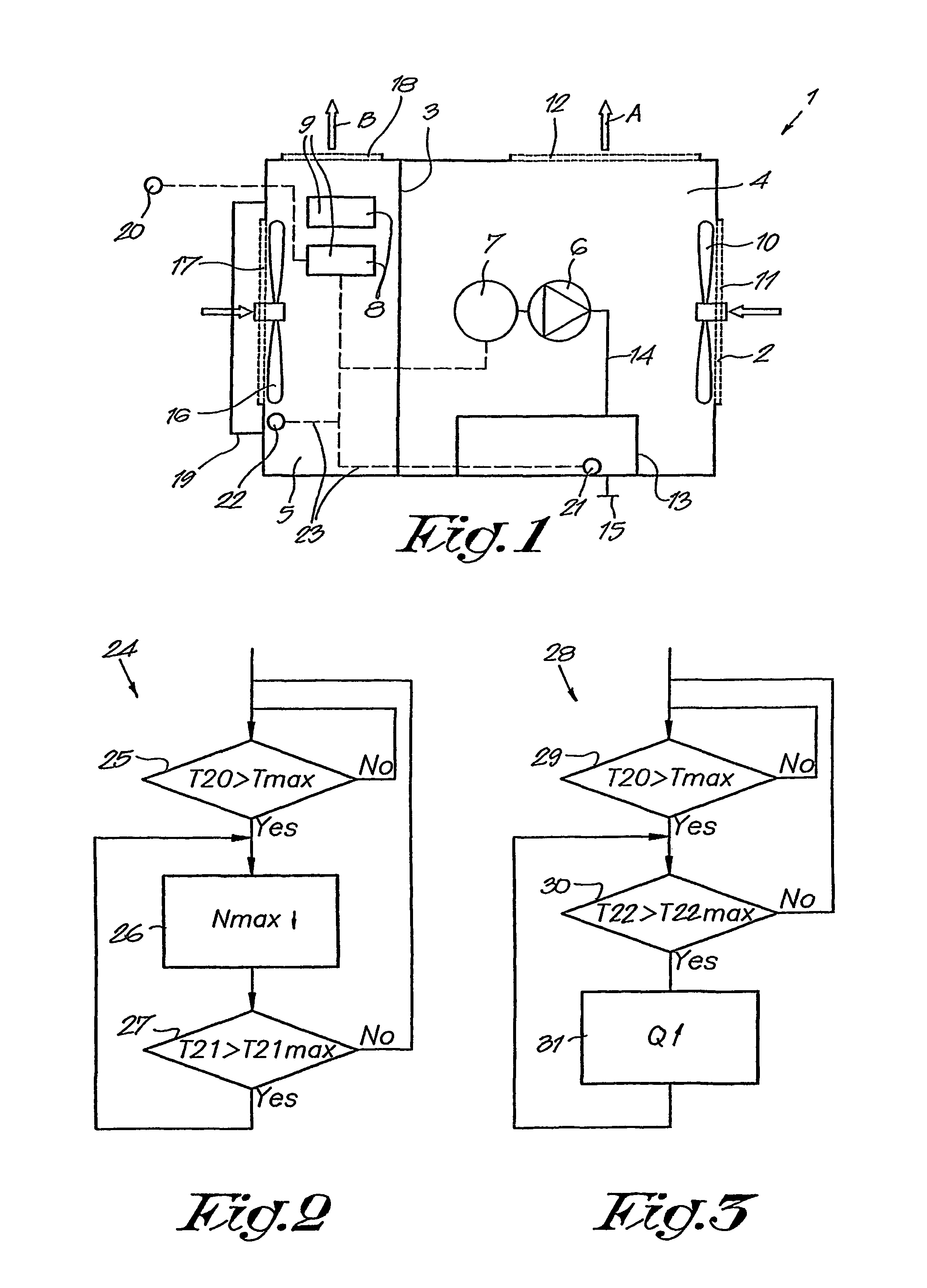
[0019]The compressor device 1 of FIG. 1 consists basically of a case or housing 2, which, in this case is divided into two compartments 4 and 5 by a wall 3, wherein in the compartment 4 a compressor element 6 is provided which is powered by a variable speed motor 7, for example a frequency controlled motor, controlled by a control box or unit 8 having a setting for a set maximum number of revolutions Nmax of the motor and a compartment 5 containing an electronic compartment wherein electronic components 9 are located, including for example the above mentioned control box 8.

[0020]The compartment 4 is cooled by an air cooling blower 10 which sucks environmental air via an inlet 11 and blows it back to the environment through the compartment 4 of the case 2 via an exhaust 12, as is shown with the arrows A. The compressor device 1 is further equipped with a cooling circuit 13, with or without a cooling medium like oil, water or similar for the cooling of the gas that is compressed by th...


PUM


Abstract

Compressor including a housing (2) containing a compressor element (6) that is powered by a variable speed motor (7) with a control box (8) with a set maximum number of revolutions (Nmax) for the compressor element (6), an air cooling blower (10) which sucks air from the environment via an inlet (11) and blows it back to the environment through the housing (2) via an exhaust (12) and a cooling circuit (13) for the cooling of the gas which has been compressed by the compressor element (6), further wherein the control box (8) is equipped with an algorithm (24) that reduces the maximum allowed set number of revolutions (Nmax) to a defined level as soon as the monitored environmental temperature (T20) rises above a maximum set level (Tmax), and the maximum allowed set number of revolutions (Nmax) is increased as soon as the environmental temperature (T20) falls below the maximum set level (Tmax).

Description

BACKGROUND[0001]A. Field[0002]The present invention concerns a compressor device.[0003]B. Related Technology[0004]More particularly the present invention concerns a compressor device of the variable speed type that basically consists of a case or housing with a compressor element therein that is powered by a variable speed motor with a fixed set maximum number of revolutions for the compressor, an air cooling blower which sucks air from the environment via an inlet and blows it via an exhaust through this case back to the environment, and a separate cooling circuit with a cooling medium for cooling of the gas which has been compressed by the compressor or cooling compressed air from the compressor.[0005]Common compressor devices are generally designed in order to be able to function in certain conditions of maximum environmental temperature, these conditions are named as the nominal working conditions.[0006]In the case that the limits of the nominal environmental conditions are exce...

Claims


Application Information

Patent Timeline
IPC IPC(8): F04C28/08F04B49/00F04B49/20
CPCF04D27/004F04B49/20F04D27/0261F04D29/584F04C28/08Y02B30/70F04B49/00
Inventor SMETS, ALEXANDER, ANTOON, FRANS, M.
Owner ATLAS COPCO AIRPOWER NV
Learn More