Cervical plate with a feedback device for selective association with bone screw blocking mechanism

a feedback device and cervical bone plate technology, applied in the field of cervical bone plate having a screw blocking mechanism, can solve problems such as loosening of bone screws

Active Publication Date: 2014-12-09
STRYKER EURO OPERATIONS HLDG LLC
View PDF51 Cites 28 Cited by
  • Summary
  • Abstract
  • Description
  • Claims
  • Application Information

AI Technical Summary

Benefits of technology

[0010]The blocking end of the blocker may be arcuate in shape such that it generally follows the arcuate shape of the bone screw hole. The arcuate shape of the blocking end may correspond to the arcuate shape of the bone screw hole, or may differ somewhat from the arcuate shape of the bone screw hole. In one aspect of the present invention, the blocker may extend over the periphery of bone screw hole by about 25% of the perimeter. In another aspect, it is about ⅓ of the periphery. Of course, as long as the blocker can be moved upon the insertion of the bone screw, the coverage on the perimeter of the bone screw hole may be larger.
[0012]In connection with another aspect of the present invention, a method may be employed practicing the steps of providing a plate having a blocker which extends over a portion of a bone screw receiving hole in a bone plate, inserting a bone screw through the bone screw receiving hole, and simultaneously moving the blocker away from the screw hole to allow insertion of the bone screw, continuing insertion until the bone screw passes the blocker to allow the blocker to move back into the blocking position, and manipulating the cam from an open orientation to a closed orientation at which movement of the blocker from the blocking position is substantially prevented.
[0013]Yet a further aspect of the present invention may be practiced by a bone plate having a top surface and a lower surface and at least two bone screw receiving holes therethrough, undercuts in the periphery of at least a portion of the bone screw receiving holes, a blocker housed within the recess, the blocker having blocking ends which extend over portions of the respective bone screw receiving holes such that the blockers in a blocking position at which it is above a bone screw seated in the plate and in a bone during implantation and can block the bone screw from backing out of the bone plate should the bone screw loosen, the blocker being movable from the blocking position upon insertion of the respective bone screw, whereby the bone screw causes the blocker to move away from the bone screw receiving hole to allow insertion until the bone screw passes the blocker and the blockers thereby permitted to return to the blocking position. In connection with this aspect of the present invention, the blocker may be seated in a recess which is coextensive with the grooves around the least portion of the periphery of the bone screw receiving holes, and the recess in the plate may include a further groove opposition the bone screw receiving holes. The aspect of the present invention may also include a blocker fixing device which, after insertion of the bone screws in the bone plate and into bone, can be actuated by a surgeon to prevent the blocker from moving from the blocking position.
[0017]In connection with this aspect of the present invention, the hinged member may include a flexible portion which facilitates locking of the hinged member in the blocking position following movement from the open position and after a bone screw is inserted into the bone screw hole.
[0020]The present invention provides a plate system wherein the bone screw, if loosened after implantation, is blocked from loosening beyond the blocker (alternatively, called the spring bar). The present invention also provides a blocking system wherein the blocker operates without requiring further actuation beyond implanting the screw past the blocker. A secondary action of a cam is provided to ensure that the movement of the bone screw does not displace the blocker upon potential backout of the bone screw. The present invention further provides the surgeon with a tactile and visual feedback as to the position of the bone screw. The feedback may result from the loss of the force exerted by the blocker on the head of the screw when the screw is tightened past the blocker. The feedback may include an audible click when the screw moves past the blocker. The feedback may also result from visual observation of the position of the blocker. The blocker may be colored to enhance such visual feedback. The feedback also comes from the secondary action of manipulating a feedback device, i.e., the cam. The simple secondary action of manipulating the cam being, in and of itself, a feedback to the surgeon, even beyond any tactile feedback from the cam.

Problems solved by technology

In many instances, there is concern that bone screws may loosen after implantation of a bone plate.

Method used


Image

  • Cervical plate with a feedback device for selective association with bone screw blocking mechanism
  • Cervical plate with a feedback device for selective association with bone screw blocking mechanism
  • Cervical plate with a feedback device for selective association with bone screw blocking mechanism

Examples


Embodiment Construction

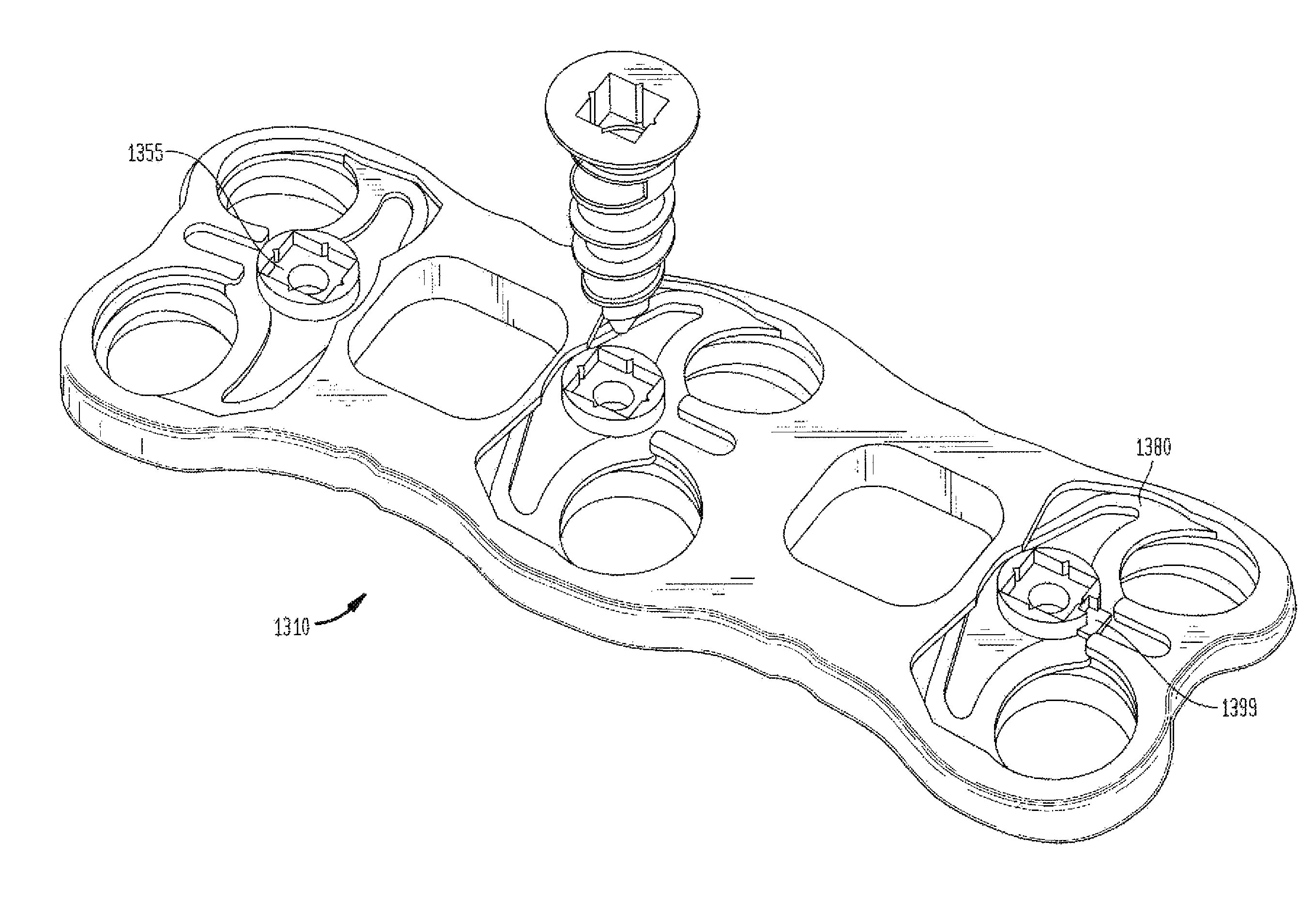
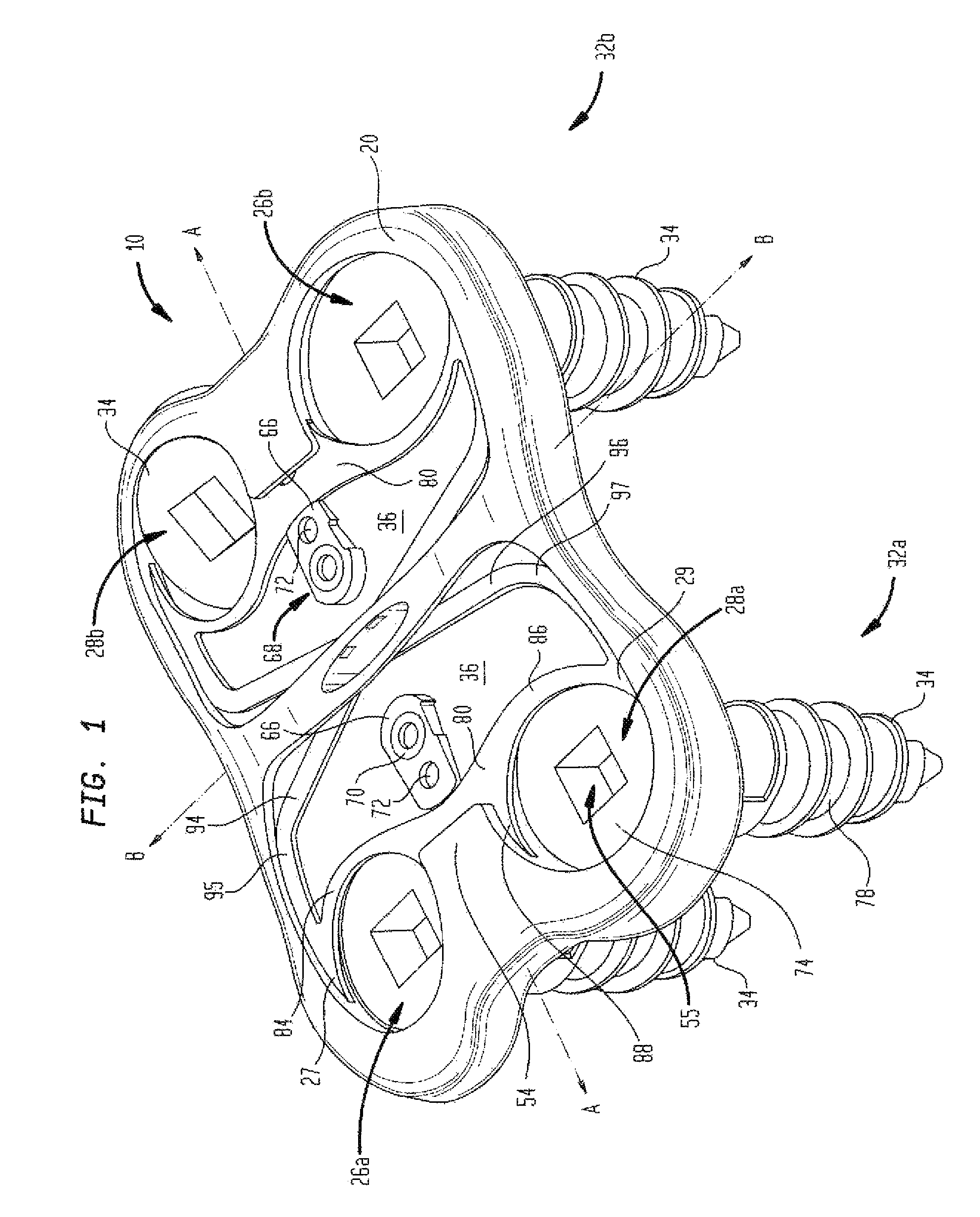
[0052]In accordance with an embodiment of the present invention, FIG. 1 depicts a one-level bone plate system 10 that may be used to stabilize or fuse vertebral bodies in the cervical or other region of the spine. System 10 is comprised of a bone plate 20, two screws 34, and blockers 80. In a more preferred embodiment, the system also includes a blocker fixation element, which may take the form of a cam 66, and a pin 70. Bone plate 20 includes a first pair 32a of screw holes 26a and 28a designed to receive bone screws 34, and likewise a second pair 32b of screw holes 26b and 28b.

[0053]It is to be understood that reference numerals pertaining to any one component are also descriptive of additional identical components of system 10, though such numerals may be omitted from the figures for clarity and ease of review. Furthermore, insofar as alternate embodiments are described, it is contemplated that a system may instead include more than one embodiment of a certain component.

[0054]Bo...


PUM


Abstract

A bone plate having at least one screw hole adapted to receive a bone screw, a blocker having a blocking end for blocking a bone screw from further backout of bone the blocker being predisposed in a blocking position wherein the blocking end at least partially overlaps a portion of the screw hole, the blocker being moveable from the blocking position by contact with the bone screw during insertion of the bone screw into the screw hole, and a blocker fixation element having an open orientation at which the blocker can move from the blocking position and a closed orientation preventing substantial movement of the blocker from the blocking position. The blocker fixation element cannot be moved to the closed orientation unless the screw head passes the blocker, thereby revealing that the blocker fixation element is in position to prevent substantial movement of the blocker.

Description

CROSS-REFERENCE TO RELATED APPLICATIONS[0001]This application claims the benefit of the filing date of U.S. Provisional Patent Application No. 61 / 002,486 filed Nov. 9, 2007 and entitled “CERVICAL PLATE WITH A FEEDBACK DEVICE FOR SELECTIVE ASSOCIATION WITH BONE SCREW BLOCKING MECHANISM,” the disclosure of which is hereby incorporated herein by reference.BACKGROUND OF THE INVENTION[0002]The present invention generally relates to a bone plate having a screw blocking mechanism. More particularly, the present invention relates to a cervical bone plate having a screw blocking mechanism that can be actuated by a tool.[0003]Bone plates and bone screws are often used in orthopedic applications. For instance, bone plates and bone screws are used in connection with the stabilization or fusion of vertebral bodies in the spine, and are also used in connection with trauma applications, for instance, in fracture fixation. In many instances, there is concern that bone screws may loosen after implan...

Claims


Application Information

Patent Timeline
Patent Type & Authority Patents(United States)
IPC IPC(8): A61B19/00A61B17/86A61B17/80A61B17/88
CPCA61B17/8888A61B2019/444A61B17/8042A61B17/888A61B17/808A61B17/8615A61B90/92
Inventor BUSH, JR., CHARLES L.BAYER, HANSPETER ROBERT
Owner STRYKER EURO OPERATIONS HLDG LLC
Why Eureka
Try Eureka