Input apparatus with haptic feedback

a technology of input apparatus and haptic feedback, which is applied in the direction of coils, electric pulse generators, magnetic measurements, etc., can solve the problems of displacement detection, no static condition, and high cost of hall sensors, and achieve the effect of reducing friction

Inactive Publication Date: 2014-12-09
FM MARKETING
View PDF5 Cites 40 Cited by
  • Summary
  • Abstract
  • Description
  • Claims
  • Application Information

AI Technical Summary

Benefits of technology

[0028]For arrangement of the magnet portions and the coils, different alternatives are provided for by the invention. In one embodiment, a movable magnet is arranged on one side of the printed circuit board whereas one or more stationary magnets are arranged on the opposite side of the printed circuit board. But arrangement of all magnets on one side of the printed circuit board is possible as well. As movable magnets, disc magnets, annular, ball-shaped or cylindrical magnets can be considered with it being also possible that a ball be inserted into the movable magnet to reduce friction which balls protrude only slightly from the magnet lower face so that no sensible tilting of the magnet occurs.

Problems solved by technology

WO 00 / 70438 points out that the Hall sensors are quite expensive and can only measure magnetic flux density so that for detecting a direction of displacement of a magnet at least two Hall sensors are required.
Disadvantageous in this apparatus, however, is that only a displacement can be detected and no static condition.

Method used


Image

  • Input apparatus with haptic feedback
  • Input apparatus with haptic feedback
  • Input apparatus with haptic feedback

Examples


Embodiment Construction

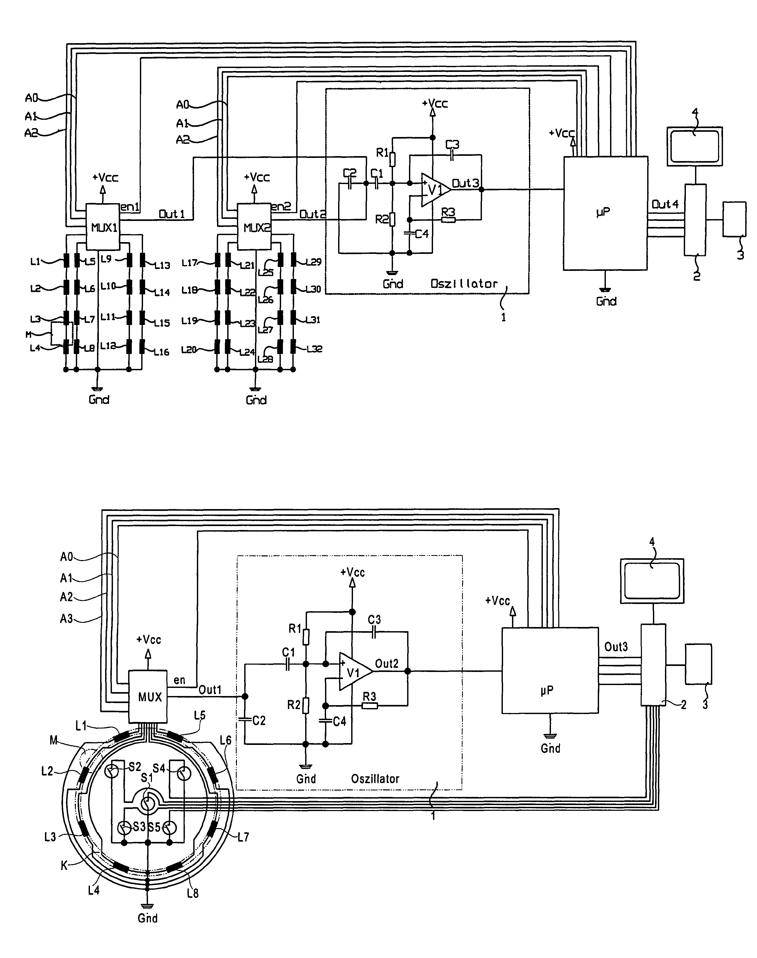
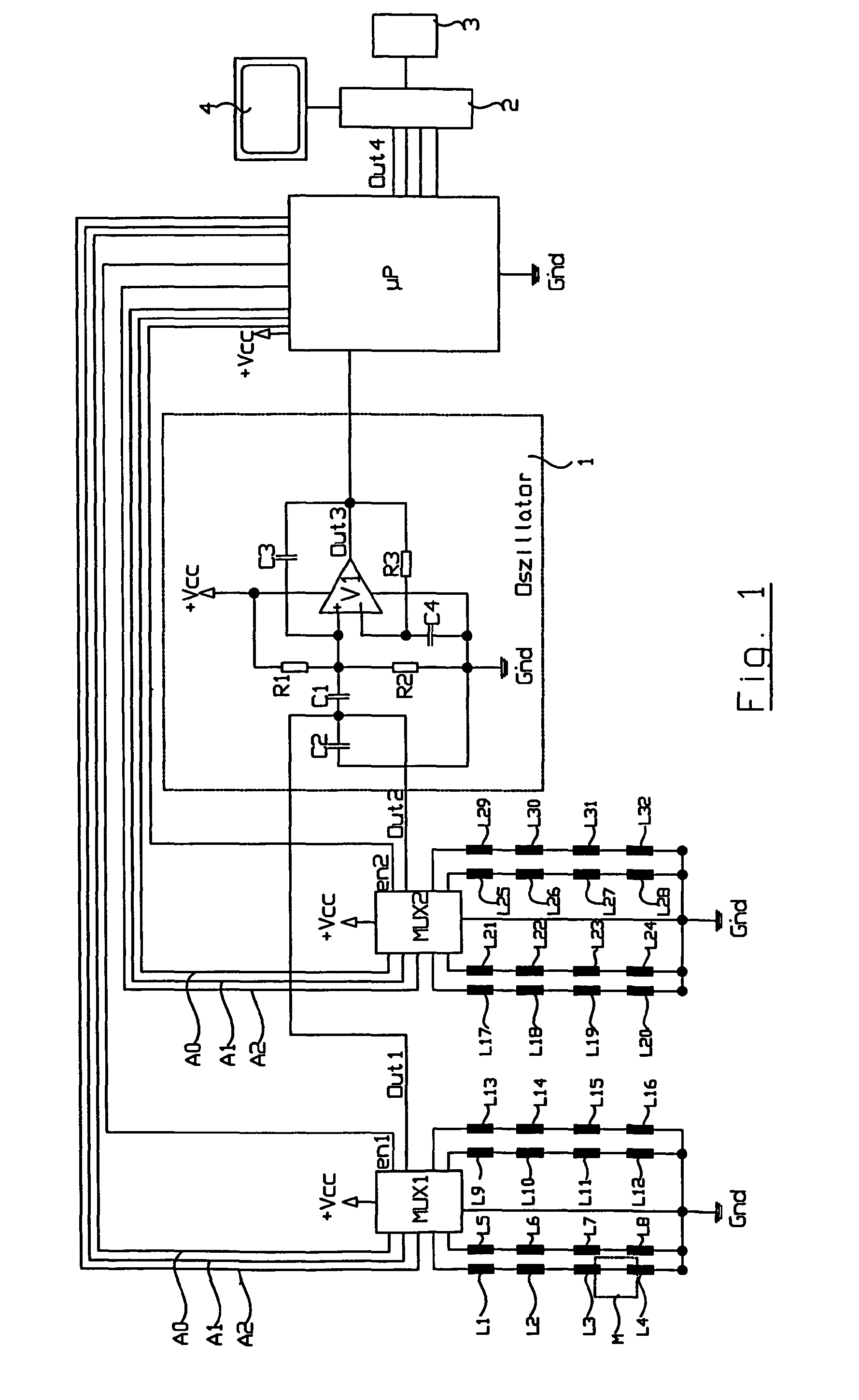
[0055]The circuit diagram of FIG. 1 shows 8 rows of inductors L1 to L32 connected in series, each individual inductor shown representing a coil which serves as a sensor for the position of a magnet M. The rows of inductors L1 to L16 are connected to a first multiplexer MUX1 and the rows of inductors L17 to L32 to a second multiplexer MUX2. Multiplexers MUX1 and MUX2 are activated by a microprocessor μP chronologically one after the other via Enable inputs EN1 and EN2, with individual inputs of the multiplexers being selected via address lines A0, A1 and / or A2, and switched through to their respective outputs OUT1 and / or OUT2. Outputs OUT1 and OUT2 of multiplexers MUX1 and MUX2 are fed to an oscillator 1 which is designed here as follows:

[0056]An operational amplifier V1 with its positive input (+) is connected to a voltage divider of resistors R1 and R2 located between supply voltage +Vcc and ground (Gnd), with the common junction of resistors R1 and R2 being connected to the two ou...


PUM


Abstract

The input device has a printed circuit board (5) to which a plurality of coils (L1-L8) has been fitted which, together with a capacitor (C2), each form a frequency-determining element of an oscillator (1). The coils (L1-L8) are arranged so as to be distributed along a path (K), which may also be a circular path. A movable magnet portion (M) can be displaced relative to the printed circuit board (5). At least one further stationary magnet portion (M1-M8) is mounted on the printed circuit board (5), which is opposite the movable magnet portion (M).

Description

REFERENCE TO RELATED APPLICATIONS[0001]This application is a U.S. national stage application of International Patent Application No. PCT / EP2011 / 001410, filed Mar. 22, 2011, and claims the benefit of German Application No. 10 2010 012 247.5, filed Mar. 22, 2010 and German Application No. 10 2010 019 596.0, filed May 5, 2010, the entire disclosures of which are incorporated herein by reference.FIELD OF THE INVENTION[0002]The invention relates to an input apparatus with haptic feedback.BACKGROUND OF THE INVENTION[0003]Many devices or objects of daily life are operated today by input apparatus such as for example electric switches, control levers, touchscreens, slide controls, keyboards and the like where feedback occurs via other sensory organs than the input. If, for example, a cursor on a monitor shall be controlled by a so-called mouse, input occurs by manual movement of the mouse whereas feedback occurs visually by viewing the monitor. If the volume of a radio shall be modified, to...

Claims


Application Information

Patent Timeline
Patent Type & Authority Patents(United States)
IPC IPC(8): G01B7/14H03K17/97G06F3/0354G06F3/0362G06F3/033G01B7/30
CPCG06F3/03548H03K17/97G06F3/0362
Inventor MAIER, FERDINANDFISCHER, THOMAS
Owner FM MARKETING
Why Eureka
Try Eureka