Tap sensitive alarm clock

a technology of alarm clock and sensitive technology, which is applied in the direction of mechanical time indication, instruments, and horology, can solve the problems of unreliability of the tapping function of such a tap sensitive alarm clock having an audio unit, and sometimes unintentionally activating the snooze function, etc., and achieves the effect of reducing noise disturbance, sensitivity adjustment, and reducing nois

Active Publication Date: 2014-12-09
KONINKLIJKE PHILIPS ELECTRONICS NV
View PDF22 Cites 2 Cited by
  • Summary
  • Abstract
  • Description
  • Claims
  • Application Information

AI Technical Summary

Benefits of technology

[0006]The measures have the effect that the sensitivity of the tap function to mechanical shock is enhanced by the filter. The filter curve is made to block frequencies occurring in the sound. Hence the filter filters frequency components that are present in the sound, so only frequency components caused by the mechanical shock acting on the vibration sensor are passed to the control circuit. The sensitivity to frequency components caused by said tapping may be increased to a required level without increasing the risk of accidental activation by the sound. Advantageously, the sound, when produced, will not trigger the control circuit to activate the respective function of the alarm clock, for example a snooze function of an alarm clock, while frequency components of the shock outside the frequency band of the audio unit are passed by the filter and will contribute to triggering the function.
[0008]In an embodiment of the alarm clock, the filter is a low-pass filter. The filter curve of the low-pass filter is easily matched to block the sound frequency range by selecting an appropriate corner frequency. Frequencies above the corner frequency are blocked, i.e. attenuated increasingly with increasing frequency above the corner frequency. It is noted that the low-pass filter may be combined with a high-pass filter having a high-pass corner frequency below the low-pass corner frequency of the low-pass filter, the combined filter also being called a band-pass filter. A practical value for the low-pass corner frequency is between 50 Hz and 200 Hz, e.g. 100 Hz. This has the advantage that sound frequencies are effectively blocked, while the frequency range to which the sensor responds is maximized without overlapping the audio range.
[0009]In an embodiment of the alarm clock, the vibration sensor is arranged for generating an electrical signal that is coupled to the filter, and the filter is arranged for processing the electrical signal. This has the advantage that electrical signals can be easily processed by electronic circuits and / or digital signal processing for filtering according to any desired filter curve.
[0011]In an embodiment of the alarm clock the filter has an adjustable amplification. This has the advantage that the sensitivity can be adjusted, e.g. to the environment or noise level of the alarm clock. In a further embodiment, the filter is arranged for adjusting the amplification in dependence on the level of the sound. Advantageously, the disturbance of the sound is reduced when the sound level is high, while the sensor is more sensitive when the sound level is low.
[0012]In an embodiment of the alarm clock the filter is arranged for adjusting the filter curve in dependence on the audio content of the sound. This has the advantage that the filtering is adjusted to the sound actually generated. In a further embodiment, the filter is a low-pass filter having a corner frequency and is arranged for adjusting the corner frequency in dependence on the audio content of the sound. The actual content of the sound is used for setting the corner frequency. Advantageously, the sensor is more sensitive when the sound contains fewer low-frequency components.
[0013]In an embodiment of the alarm clock the audio circuit comprises a high-pass filter having a high-pass filter curve to control the frequencies occurring in the sound. This has the advantage that the contents of sound are controlled so that fewer low-frequency components are generated.

Problems solved by technology

It appeared that the tapping function of such a tap sensitive alarm clock having an audio unit is not reliable, for example, in that the snooze function is sometimes activated unintentionally.

Method used


Image

  • Tap sensitive alarm clock
  • Tap sensitive alarm clock
  • Tap sensitive alarm clock

Examples


Embodiment Construction

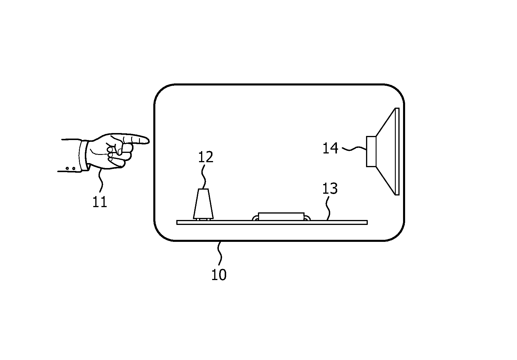
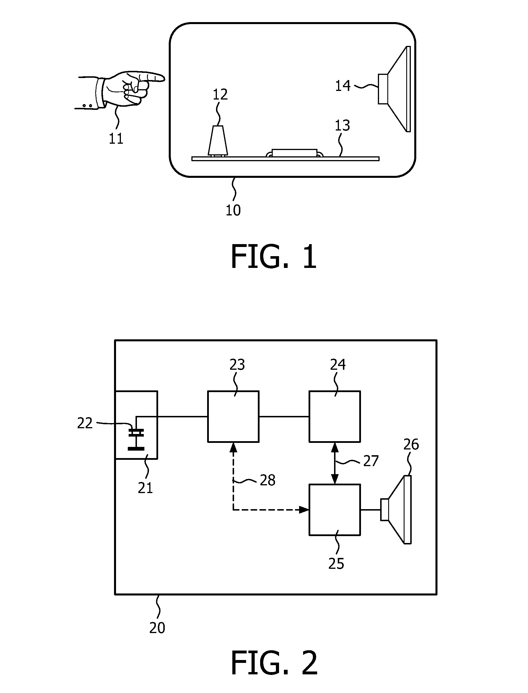
[0025]FIG. 1 shows a tap sensitive alarm clock. The alarm clock has a housing 10. A user may tap on the housing to activate a function of the alarm clock, as indicated by a user's hand 11, in any appropriate way (slamming, banging, knocking, etc). Thereby a mechanical shock is applied to the housing. A vibration sensor 12 is mechanically coupled to the housing, e.g. by locating the sensor on the inside against a wall or against an inner element of the housing. In the Figure, the sensor is located on an electronic circuit board 13 that is mechanically attached to the housing. The function of the electronic board according to the invention is discussed in detail with reference to FIG. 2, and may further comprise any known function for an alarm clock operated by a human user. Also devices similar to the alarm clock, like a kitchen appliance, a gaming device, etc may be provided with the tap sensitive function according to the invention. The device further has an audio output element su...


PUM


Abstract

A tap sensitive alarm clock has a housing (20), a vibration sensor (22) mechanically coupled to the housing for receiving a shock due to a user tapping the housing, and a control circuit (24) coupled to the vibration sensor for controlling a function of the alarm clock. An audio unit (26) is coupled to an audio circuit (25) for generating sound, e.g. a loudspeaker in an alarm clock or a wake up light. To avoid interference of the sound and the vibration sensor, the alarm clock is provided with a filter (23) coupled to the vibration sensor and the control circuit. The filter has a filter curve matched to block frequencies occurring in the sound. Advantageously it is avoided that the sound frequencies trigger the function, while the sensor is sensitive to other frequencies up to the frequency range of the sound for reliably detecting the tapping.

Description

FIELD OF THE INVENTION[0001]The invention relates to a tap sensitive alarm clock, comprising a housing, a vibration sensor mechanically coupled to the housing for receiving a shock due to a user tapping the housing, and a control circuit coupled to the vibration sensor for controlling a function of the alarm clock.BACKGROUND OF THE INVENTION[0002]Document EP 1 833 103 describes a shock-activated switch device, which comprises a piezoelectric buzzer having a body for receiving a mechanical shock and a terminal for outputting an electrical output signal when the body receives a mechanical shock. The shock is provided by a user tapping the housing of the device. An output circuit is connected to the terminal for converting the output signal into a logic signal for controlling an electronic circuit to execute a specific programmable function, such as alarm snooze.SUMMARY OF THE INVENTION[0003]A tap sensitive alarm clock, like the above shock sensitive device, has a vibration sensor, but...

Claims


Application Information

Patent Timeline
Patent Type & Authority Patents(United States)
IPC IPC(8): G04G13/02G04B21/00G04C23/00G04B23/02G04G21/08G04C21/00G04C21/16
CPCG04G13/028G04G21/08G04G13/023G04G13/021
Inventor HEERINGA, SCHELTEWIND, ROELOF JANROZEBOOM, FRANS WIEBEBOTMA, JACOB HENDRIKVAN OOSTRUM, HIELKE SIMONSCHALLIG, MICHIEL ALLAN AURELIUSGODLIEB, ROBERT
Owner KONINKLIJKE PHILIPS ELECTRONICS NV
Why Eureka
Try Eureka