
Device and method for fast block-matching motion estimation in video encoders

a video encoder and motion estimation technology, applied in the compression field of images, can solve the problem of one of the most computationally complex processes within the video encoder, and achieve the effect of reducing the complexity of the motion estimation process and reducing the performan

Inactive Publication Date: 2014-12-16
FASTVDO
View PDF2 Cites 9 Cited by
  • Summary
  • Abstract
  • Description
  • Claims
  • Application Information

AI Technical Summary

Benefits of technology

[0016]The invention herein represents a highly efficient fast motion estimation scheme for finding such redundancies in previous frames. The scheme allows for significant complexity reduction within the motion estimation process. It therefore also reduces complexity of the entire video encoder with minimal impact on compression efficiency and reconstruction quality. The invention uses adaptive consideration of efficient predictors, adaptation of patterns and thresholds, and use of additional advanced criteria. The method is applicable to different types of implementations or systems (i.e. hardware or software).
[0019]As with motion vectors, distortion of adjacent blocks tends to be highly correlated. The early termination process uses this correlation, thereby enabling complexity reduction of the motion estimation process. If the early termination criteria are not satisfied, motion estimation is refined further by using an iterative search pattern localized at the best predictor within set S. The method disclosed herein optionally considers several possible patterns, including the patterns of PMVFAST and APDZS, Hexagonal patterns, and others. The preferred embodiments use three simple patterns. In view of the fact that equation 1 could lead to local minima (mainly due to the effect of λMOTION)that could potentially lead to relatively reduced performance, the refinement pattern is not localized only around the best predictor but, if appropriate conditions are satisfied, also repeated around the second best candidate. Optionally the process of going to successive next best candidates can be repeated until candidates are exhausted.

Problems solved by technology

It is a key component of video coding technologies, and is one of the most computationally complex processes within a video encoding system.

Method used


Image

  • Device and method for fast block-matching motion estimation in video encoders
  • Device and method for fast block-matching motion estimation in video encoders
  • Device and method for fast block-matching motion estimation in video encoders

Examples


Embodiment Construction

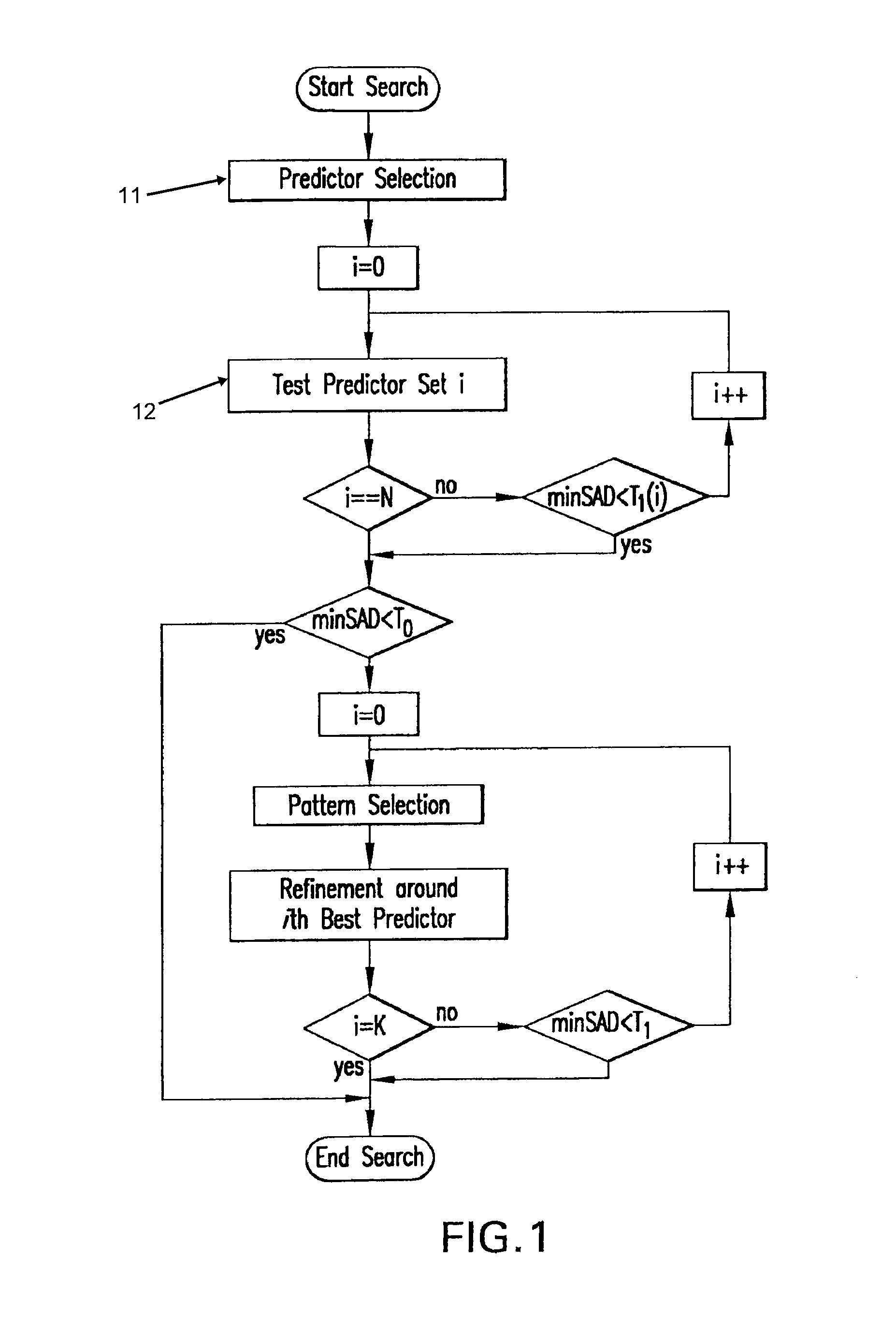
[0031]FIG. 11 is a flow diagram of the general scheme for finding redundancies between frames currently undergoing compression and prior frames. This flow diagram shows a process of searching prior frames for redundancies using patterns to be discussed below. The efficiency of the method derives from effective choice of patterns and astute choice of order of search. The method is designed for the earliest termination of a motion estimation search. The key feature of this invention is finding the best pattern subsets to search, the predictors to select given the patterns, and the order of search.

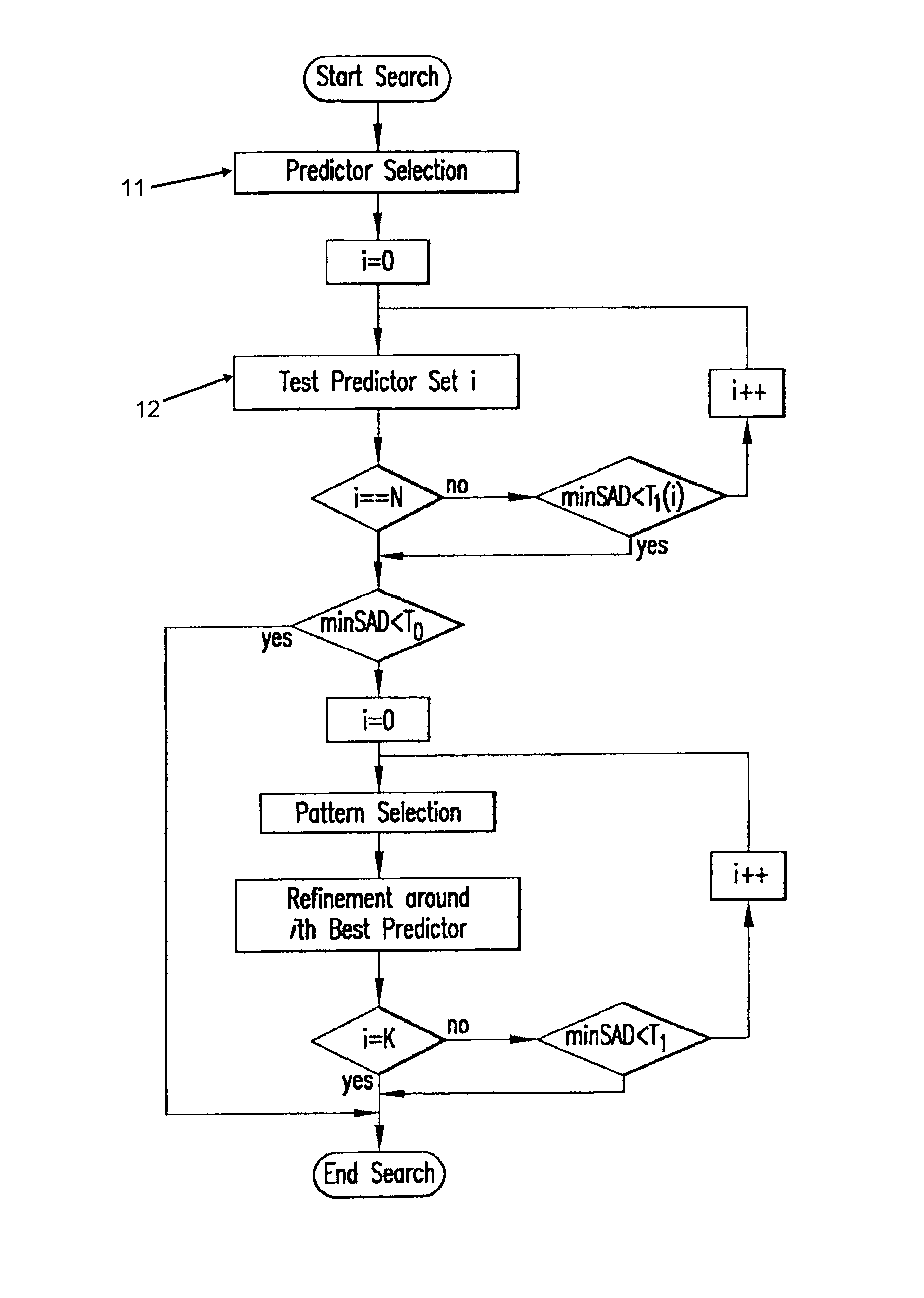
[0032]FIG. 1 shows an overview flow diagram of the motion vector estimation scheme of this invention. The first step 11 is Predictor Selection. In the first iterative substep 12, the system uses a Test Predictor Set selected as is explained below. The “best” set is chosen as the one that minimizes Equation 1 above to find the “best” SAD as defined in Equation 2 above. If the value of SAD is b...


PUM


Abstract

Motion estimation is the science of predicting the current frame in a video sequence from the past frame (or frames), by slicing it into rectangular blocks of pixels, and matching these to past such blocks. The displacement in the spatial position of the block in the current frame with respect to the past frame is called the motion vector. This method of temporally decorrelating the video sequence by finding the best matching blocks from past reference frames—motion estimation—makes up about 80% or more of the computation in a video encoder. In this patent disclosure, we define a method of searching only a very sparse subset of possible displacement positions (or motion vectors) among all possible ones, to see if we can get a good enough match, and terminate early. This sparse subset of motion vectors is preselected using prior knowledge and extensive testing on video sequences.

Description

CROSS REFERENCE TO RELATED APPLICATIONS[0001]This application claims benefit of priority from U.S. Provisional Patent Application No. 60 / 671,147, filed Apr. 14, 2005.FIELD OF THE INVENTION[0002]The invention relates to the compression of images for storage or transmission and for subsequent reconstruction of an approximation of the original image. More particularly, it relates to the coding of video signals for compression and subsequent reconstruction. Most particularly, it relates to the use of the technique of motion estimation as a means of providing significant data compression with respect to video signals so that they may subsequently be reconstructed with minimal observable information loss.BACKGROUND OF THE INVENTION[0003]In general video transmission involves sending over wire, by radio signal, or otherwise very rapid successive frames of images. In the modern world, video transmission increasingly involves transmission of digital video. Each frame of a video stream is a s...

Claims


Application Information

Patent Timeline
Patent Type & Authority Patents(United States)
IPC IPC(8): H04N19/56H04N7/24H04N19/53H04N19/533
CPCH04N19/533H04N19/527H04N19/52H04N19/56H04N19/139H04N19/53H04N19/513H04N19/176H04N19/42H04N19/567H04N19/147H04N19/43
Inventor TOURAPIS, ALEXIS MICHAELCHEONG, HYE-YEONTOPIWALA, PANKAJ N.
Owner FASTVDO
Learn More