Circulated pneumatic tube transit system

a pneumatic tube and transit system technology, applied in the direction of sustainable transportation, transportation and packaging, ways, etc., can solve the problems of limited speed of all means of transportation, difficult to commercialize, and rarely helps in the majority of means of transportation

Inactive Publication Date: 2014-12-23
ZHOU BO
View PDF17 Cites 28 Cited by
  • Summary
  • Abstract
  • Description
  • Claims
  • Application Information

AI Technical Summary

Problems solved by technology

However, all of them have to deal with fluid resistance from air.
Regardless of the effort, the fluid (air or water) resistance at high speed is too much to conquer which resulted in the limited speed of all means of transportation.
The cause of these problems is fluid (air or water) is mostly still with the exception of movement in the form of currents (winds or ocean current) in random directions, which rarely helps in most means of transportation (gliders and sail boats are exceptions, but they can be difficult to commercialize).
Evacuated Tube Transport (ETT) (see U.S. Pat. No. 5,950,543, Evacuated Tube Transport) was invented to transport capsules in an evacuated tube where the air resistance could theoretically be reduced to zero, but the ETT is extremely difficult to implement.
An alternative (see WO2012079114, An Evacuated Tube Transport System) was proposed to the ETT, but to the applicant's knowledge, none have been successfully implemented.
The reason is because current designs are not efficient enough or economically viable to transport passengers or cargo in a capsule over long distances.

Method used


Image

  • Circulated pneumatic tube transit system
  • Circulated pneumatic tube transit system
  • Circulated pneumatic tube transit system

Examples


Embodiment Construction

[0018]All illustrations of the drawings are for the purpose of describing selected versions of the present invention and are not intended to limit the scope of the present invention.

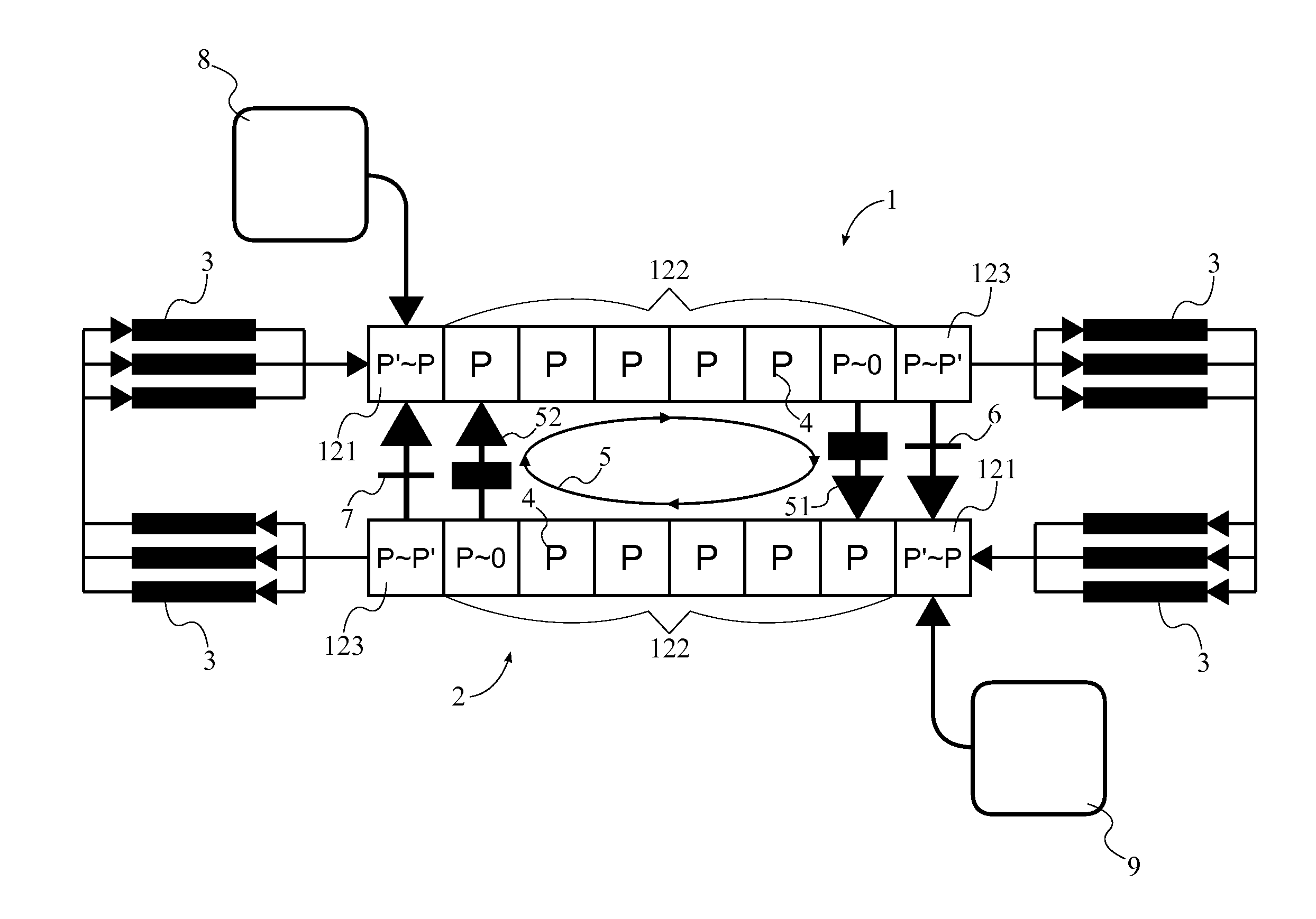
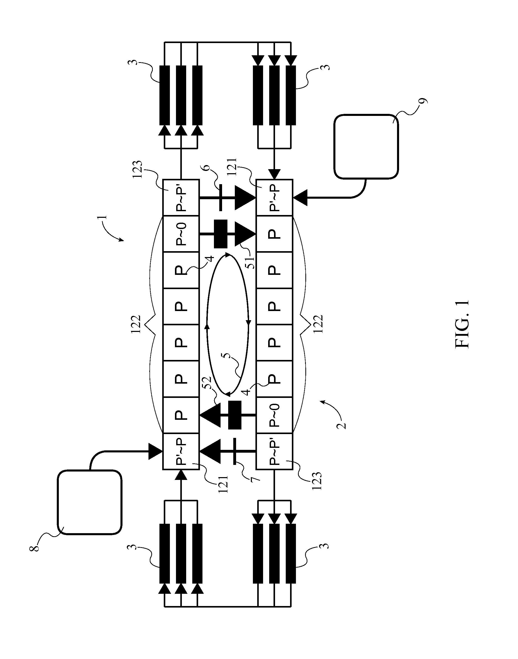
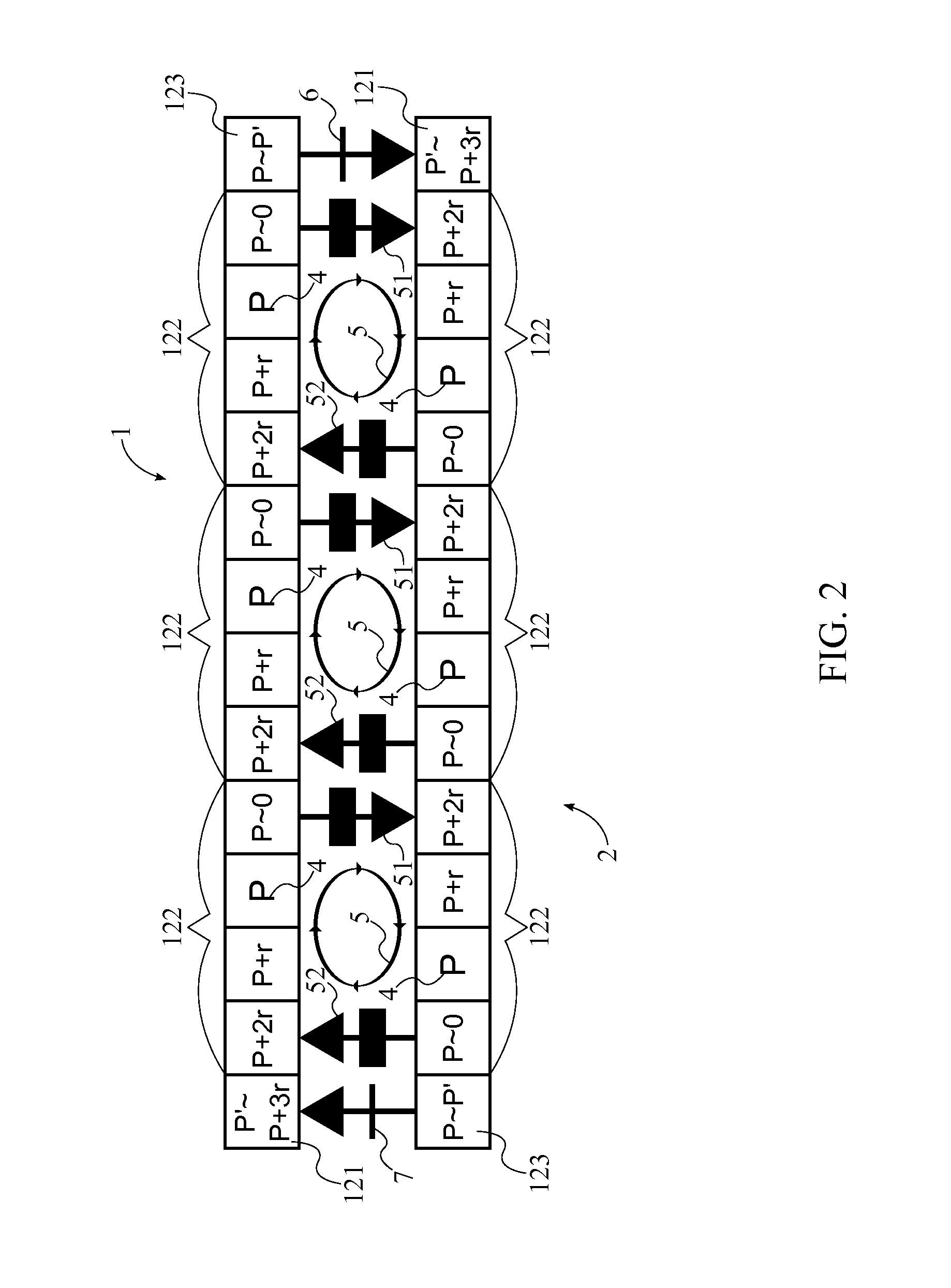
[0019]As can be seen in FIG. 1, the present invention is a circulated pneumatic tube transit system that conserves the kinetic energy of cruising capsules and recycles the kinetic energy of arriving capsule in order to launch a departing capsule in the opposite direction. The present invention mainly comprises a first tube 1, a second tube 2, a plurality of capsules 3, a volume of air 4, an at least one fluid loop mechanism 5, a first one-directional valve 6, a second-one directional valve 7, a first pressure tank 8, and a second pressure tank 9. The first tube 1 and the second tube 2 are opposing pathways that allow the plurality of capsules 3 to travel back and forth along a predetermined route. The plurality of capsules 3 is the means by which the present invention carries either passengers or cargo a...


PUM


Abstract

A circulated pneumatic tube transit system is used to transport passengers / cargo along a pair of pneumatic tubes, which are positioned along each other. Capsules are movably suspended within the tubes by either a maglev system or wheels. The capsules travel in opposite directions in each tube so that the system provides back and forth transportation between two destinations. A fluid loop mechanism cycles a volume of air through the tubes as a means to propel the capsules through each tube. A series of fluid loop mechanism can be air multipliers as the volume of air cycles through the tubes. Two one-directional valves are located at opposite ends of the tubes and are used to transfer the kinetic energy for an arriving capsule within one tube into kinetic energy for a departing capsule within the other tube.

Description

[0001]The current application claims a priority to the U.S. Provisional Patent application Ser. No. 61 / 823,195 filed on May 14, 2013.FIELD OF THE INVENTION[0002]The present invention is generally related to a mass transit system capable of running at extremely low energy consumption level, more specifically, to an ultra efficient circulated fluid (e.g. air) driven capsules in a pair of parallel pneumatic tubes by conserving and recycling the kinetic energy of the capsules.BACKGROUND OF THE INVENTION[0003]For centuries, scientists and engineers have been fighting with all kinds of medium induced resistance in the form of drag and friction. Wheels were invented to reduce the sliding friction from the ground; catamarans were invented to reduce the skin friction from water; and airplanes and maglev trains were invented to eliminate the rolling friction from wheels touching the ground. However, all of them have to deal with fluid resistance from air. Millions of dollars were spent on aer...

Claims


Application Information

Patent Timeline
Patent Type & Authority Patents(United States)
IPC IPC(8): B61B13/08B61B13/10
CPCB61B13/08B61B13/10Y02T30/00
Inventor ZHOU, BO
Owner ZHOU BO
Why Eureka
Try Eureka