Vehicle brake fluid pressure control apparatus

a brake fluid and control apparatus technology, applied in the direction of brake systems, etc., can solve the problem of not being able to set the allowable differential pressure to sufficiently large values, and achieve the effect of accurate judging a road surface, sufficient allowable differential pressure, and high friction coefficien

Active Publication Date: 2014-12-23
AUTOLIV NISSIN BRAKE SYST JAPAN CO LTD
View PDF25 Cites 2 Cited by
  • Summary
  • Abstract
  • Description
  • Claims
  • Application Information

AI Technical Summary

Benefits of technology

[0006]The present invention has been made in view of the circumstances described above and an object thereof is to provide a vehicle brake fluid pressure control apparatus capable of accurately judging a road surface having a high friction coefficient and setting sufficiently large allowable differential pressures.

Problems solved by technology

Accordingly, the apparatus has such a problem that the apparatus cannot accurately judge that the vehicle is running on a road surface having a high friction coefficient upon setting the allowable differential pressures and thereby cannot set the allowable differential pressures to sufficiently large values.

Method used


Image

  • Vehicle brake fluid pressure control apparatus
  • Vehicle brake fluid pressure control apparatus
  • Vehicle brake fluid pressure control apparatus

Examples


Embodiment Construction

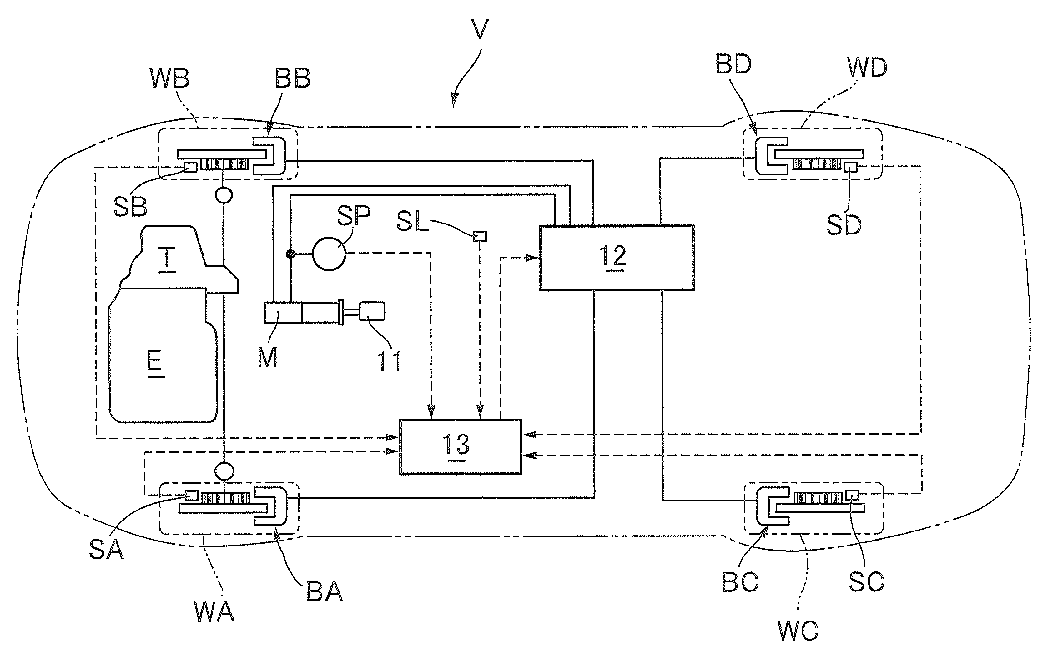
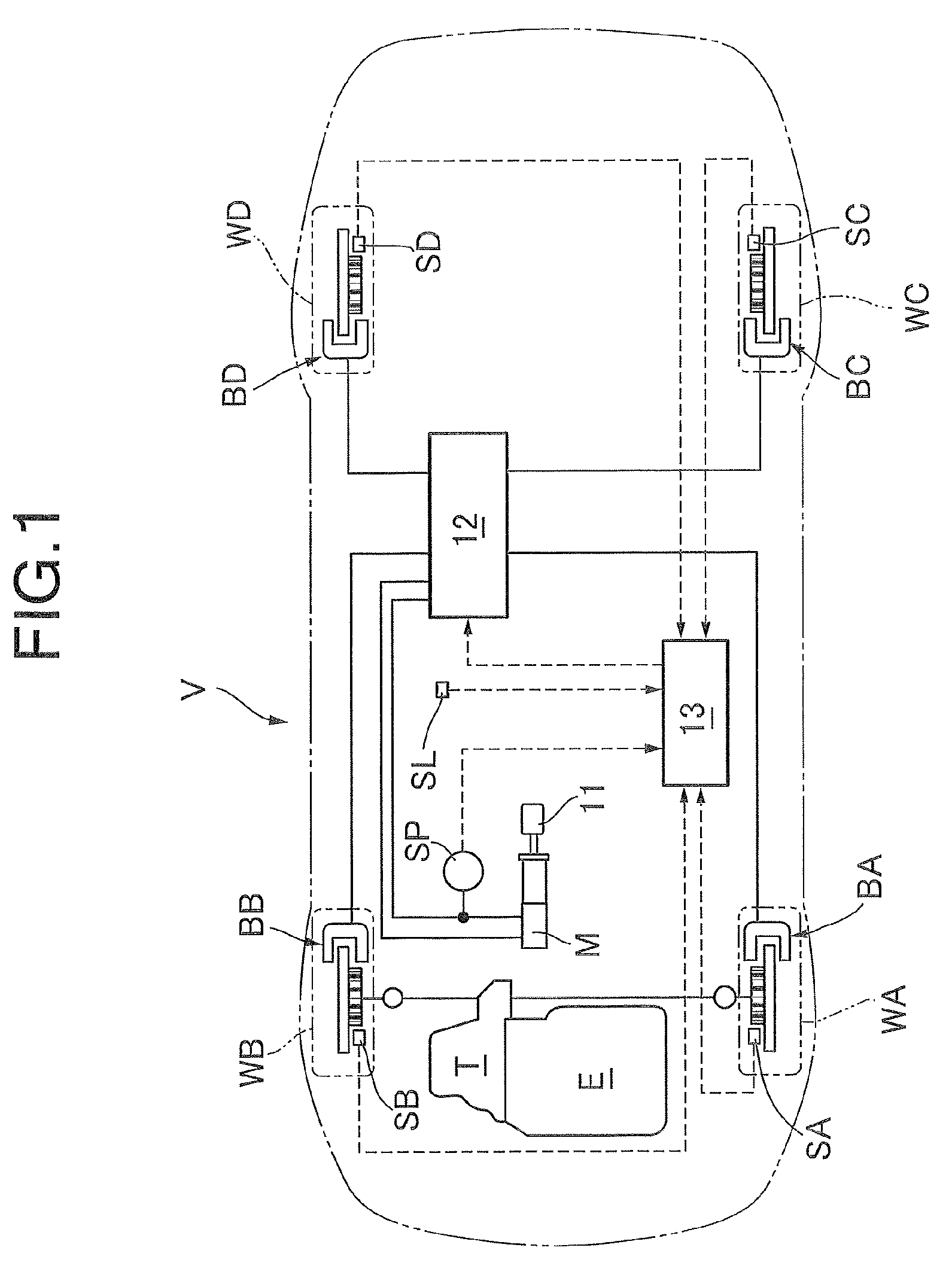
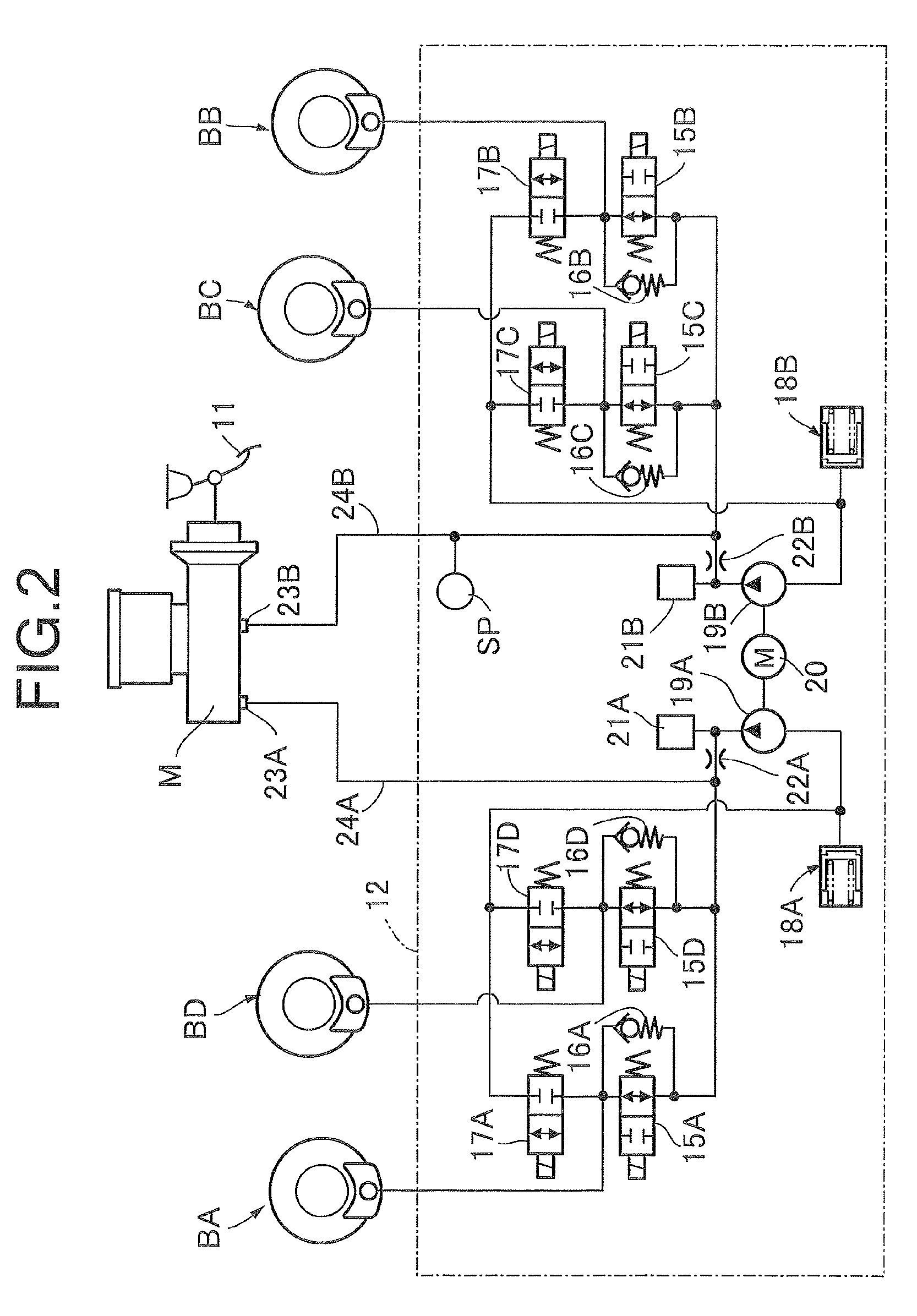
[0030]An embodiment of the present invention is described with reference to attached FIGS. 1 to 10B. First, in FIG. 1, a vehicle V includes: left and right coaxial front wheels WA and WB to which a driving force of an engine E is transmitted via a transmission T; and left and right coaxial rear wheels WC and WD. A brake pedal 11 operated by a driver is connected to a master cylinder M. Wheel brakes BA, BB, BC, and BD which operate by actions of brake fluid pressures are provided respectively in the front wheels WA and WB and the rear wheels WC and WD. The master cylinder M is connected to the wheel brakes BA to BD via a fluid pressure adjusting unit 12. The fluid pressure adjusting unit 12 is capable of performing adjustment of individually increasing and decreasing the brake fluid pressures acting on the wheel brakes BA to BD to prevent the wheels from locking during braking.

[0031]The operation of the fluid pressure adjusting unit 12 is controlled by a fluid pressure control appara...


PUM


Abstract

A vehicle brake fluid pressure control apparatus controls operations of a fluid pressure adjusting unit capable of performing adjustment of individually increasing and decreasing brake fluid pressures acting respectively on wheel brakes for front wheels and wheel brakes for rear wheels to be within allowable differential pressures allowable between the brake fluid pressures of the wheel brakes for the left and right coaxial front wheels and the left and right coaxial rear wheels. In the apparatus, estimated vehicle body deceleration calculator calculates an estimated vehicle body deceleration of a vehicle and allowable differential pressure setting device sets the allowable differential pressures matching a road surface friction coefficient based on the estimated vehicle body deceleration calculated by the estimated vehicle body deceleration calculator. This enables accurate judgment of a road surface having a high friction coefficient and setting of sufficiently large allowable differential pressures.

Description

BACKGROUND OF THE INVENTION[0001]1. Field of the Invention[0002]The present invention relates to a vehicle brake fluid pressure control apparatus including: a fluid pressure adjusting unit capable of performing adjustment of individually increasing and decreasing brake fluid pressures acting respectively on wheel brakes for front wheels and wheel brakes for rear wheels so as to prevent the front wheels and the rear wheels from being locked during braking; and allowable differential pressure setting means for setting allowable differential pressures allowable between the brake fluid pressures of the wheel brakes for the left and right coaxial front wheels and between the brake fluid pressures of the wheel brakes for the left and right coaxial rear wheels, the operation of the fluid pressure adjusting unit being controlled in such a way that each of the differential pressures between the brake fluid pressures of the wheel brakes for the left and right coaxial front wheels and between ...

Claims


Application Information

Patent Timeline
Patent Type & Authority Patents(United States)
IPC IPC(8): B60T8/176B60T8/1764
CPCB60T2210/124B60T8/1764
Inventor SEKIYA, TOMOAKI
Owner AUTOLIV NISSIN BRAKE SYST JAPAN CO LTD
Why Eureka
Try Eureka