Transmission unit with reduced crosstalk signal
a transceiver and crosstalk technology, applied in the field of transceivers, can solve the problems of reducing affecting the efficiency of transceivers, and affecting the efficiency of transceivers, and achieves the effects of reducing the cost of assembling, and improving the efficiency of assembling
- Summary
- Abstract
- Description
- Claims
- Application Information
AI Technical Summary
Benefits of technology
Problems solved by technology
Method used
Image
Examples
second embodiment
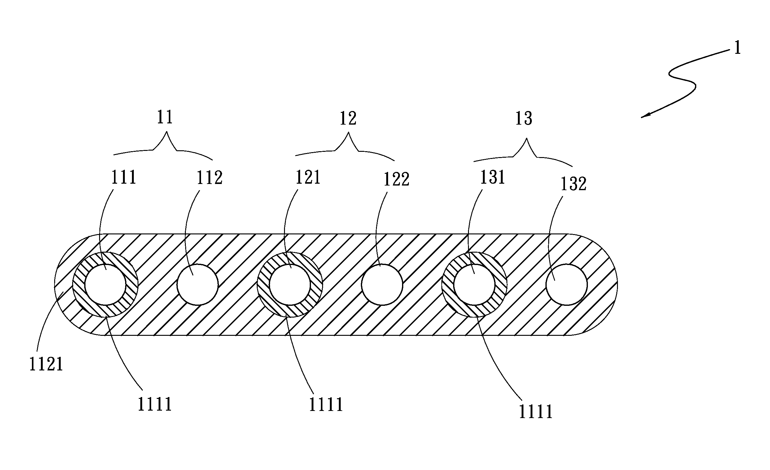
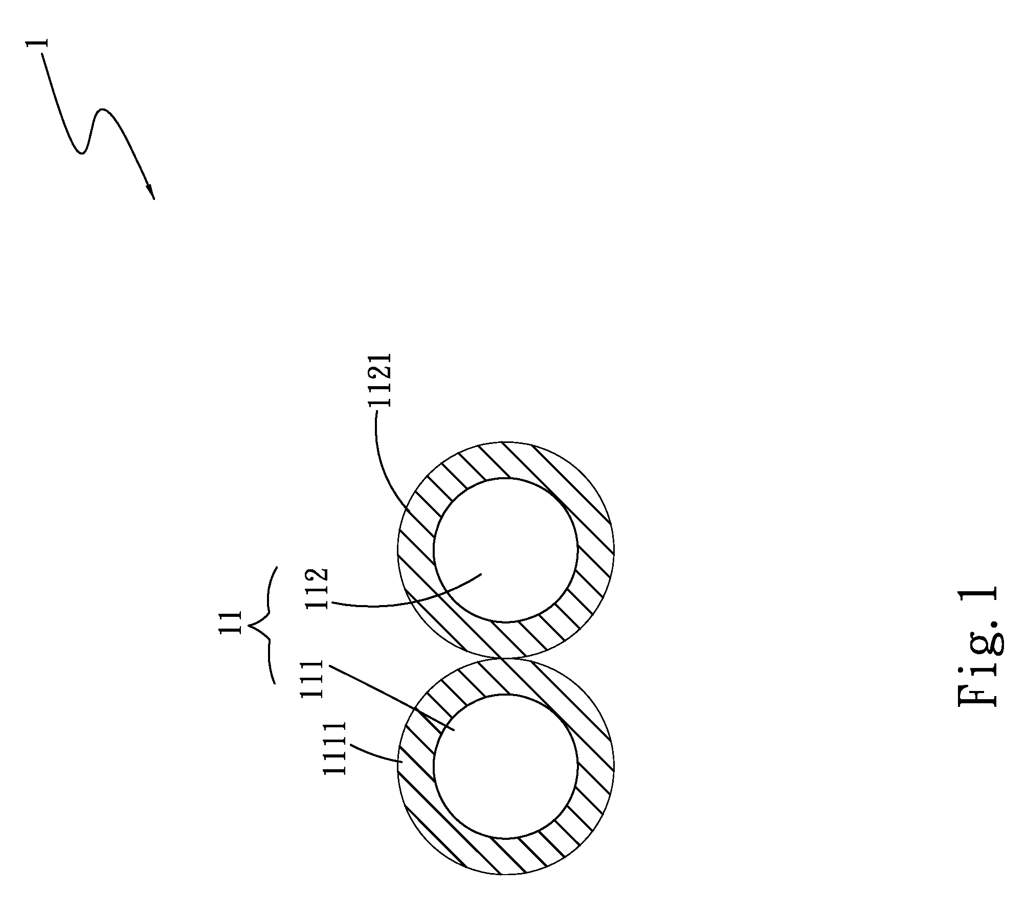
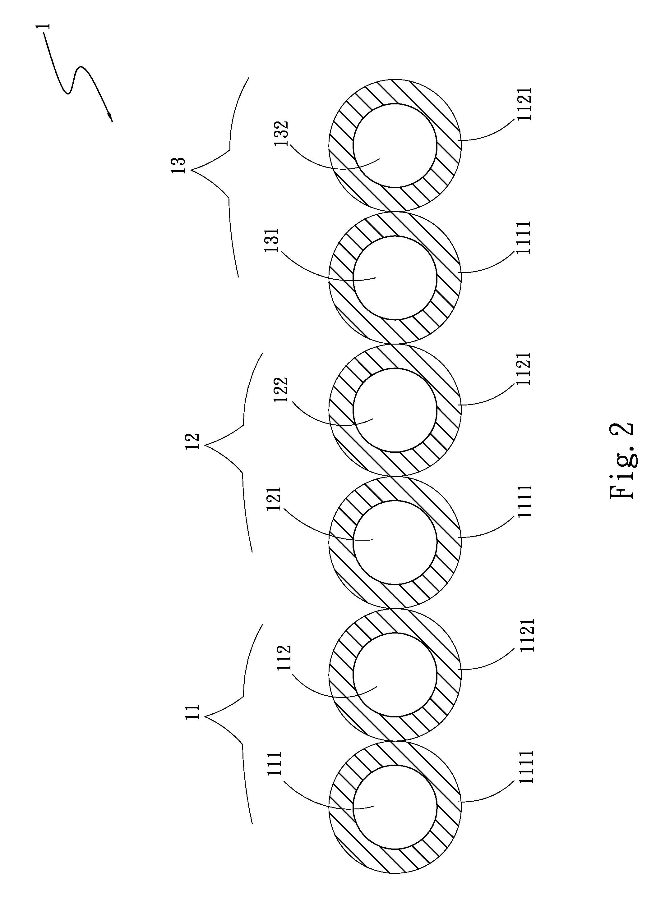
[0027]In the second embodiment, there is a difference between the dielectric values of the first sheath 1111 and the second sheath 1121. Since a high-dielectric material has good ability to concentrate electric field, the use of a low-dielectric material for one conductor in each of the signal pairs can reduce electric field concentration and accordingly, reduce crosstalk noise interference between the signal pairs.
[0028]FIG. 3 is a cross sectional view of a transmission unit 1 according to a third embodiment of the present invention. As shown, in the third embodiment, the transmission unit 1 includes a first conductor group 11 having at least one first conductor 111 surrounded by a first sheath 1111 and at least one second conductor 112; a second conductor group 12 having at least one third conductor 121 surrounded by a first sheath 1111 and at least one fourth conductor 122; a third conductor group 13 having at least one fifth conductor 131 surrounded by a first sheath 1111 and at...
fourth embodiment
[0030]In the fourth embodiment, the transmission unit 1 includes differential signal pairs and earth conductors. There is a difference between the dielectric values of the first and second sheaths 1111, 1121 and the third sheath 1113. Since a high-dielectric material has good ability to concentrate electric field, the use of a low-dielectric material for one conductor in each of the signal pairs can reduce electric field concentration and accordingly, reduce crosstalk noise interference between the signal pairs.
[0031]FIG. 5 is a cross sectional view of a transmission unit 1 according to a fifth embodiment of the present invention. As shown, in the fifth embodiment, the transmission unit 1 includes a first conductor group 11 having at least one first conductor 111 surrounded by a first sheath 1111 and at least one second conductor 112 surrounded by a second sheath 1121; a second conductor group 12 having at least one third conductor 121 surrounded by a first sheath 1111 and at least ...
fifth embodiment
[0032]Alternatively, the transmission unit 1 in the fifth embodiment may include differential signal pairs without earth conductors. There are differences between the dielectric values of the first, the second and the third sheath 1111, 1121, 1113. Since a high-dielectric material has good ability to concentrate electric field, the use of a low-dielectric material for one conductor in each of the signal pairs can reduce electric field concentration and accordingly, reduce crosstalk noise interference between the signal pairs.
[0033]FIG. 6 is a cross sectional view of a transmission unit 1 according to a sixth embodiment of the present invention. As shown, in the sixth embodiment, the transmission unit 1 includes a first conductor group 11 having at least one first conductor 111 surrounded by a first sheath 1111 and at least one second conductor 112; and a second sheath 1121 surrounding the first sheath 1111 and the second conductor 112. The first and the second conductor 111, 112 are...
PUM
 Abstract
Description
Claims
Application Information
 - R&D
- Intellectual Property
- Life Sciences
- Materials
- Tech Scout
- Unparalleled Data Quality
- Higher Quality Content
- 60% Fewer Hallucinations
Browse by: Latest US Patents, China's latest patents, Technical Efficacy Thesaurus, Application Domain, Technology Topic, Popular Technical Reports.
© 2025 PatSnap. All rights reserved.Legal|Privacy policy|Modern Slavery Act Transparency Statement|Sitemap|About US| Contact US: help@patsnap.com


