Transmission unit with reduced crosstalk signal

a crosstalk signal and transceiver technology, applied in the field of transceiver, can solve the problems of reducing and so as to improve the efficiency of the transmission unit. , the effect of reducing the cost of the transmission uni

Active Publication Date: 2013-01-17
YES WAY ENTERPRISE CORP
View PDF4 Cites 188 Cited by
  • Summary
  • Abstract
  • Description
  • Claims
  • Application Information

AI Technical Summary

Benefits of technology

[0004]It is therefore a primary object of the present invention to provide a transmission unit that can reduce crosstalk occurred during high-speed signal transmission over the transmission unit.
[0006]In the present invention, there is a dielectric difference between the first sheath and the second sheath. When the first conductor is surrounded by the first sheath made of a high-dielectric material, the first conductor would have higher dielectric coefficient than the second conductor. In other words, when the first sheath has a high dielectric coefficient, the first conductor surrounded by the first sheath would correspondingly have a high dielectric coefficient. Since the high-dielectric coefficient material has good ability of concentrating electric field to enable easy storage of electric field energy, the transmission unit including the first conductor surrounded by the high-dielectric first sheath can reduce the crosstalk occurred during high-speed signal transmission over the transmission unit.

Problems solved by technology

While the metal shield can reduce the crosstalk between the signal pair, it makes the whole cable stiff, heavy and inconvenient for use.
Moreover, cables with conductors surrounded by metal shields could not be used with piercing terminals to enable automated assembling of cables.

Method used


Image

  • Transmission unit with reduced crosstalk signal
  • Transmission unit with reduced crosstalk signal
  • Transmission unit with reduced crosstalk signal

Examples


second embodiment

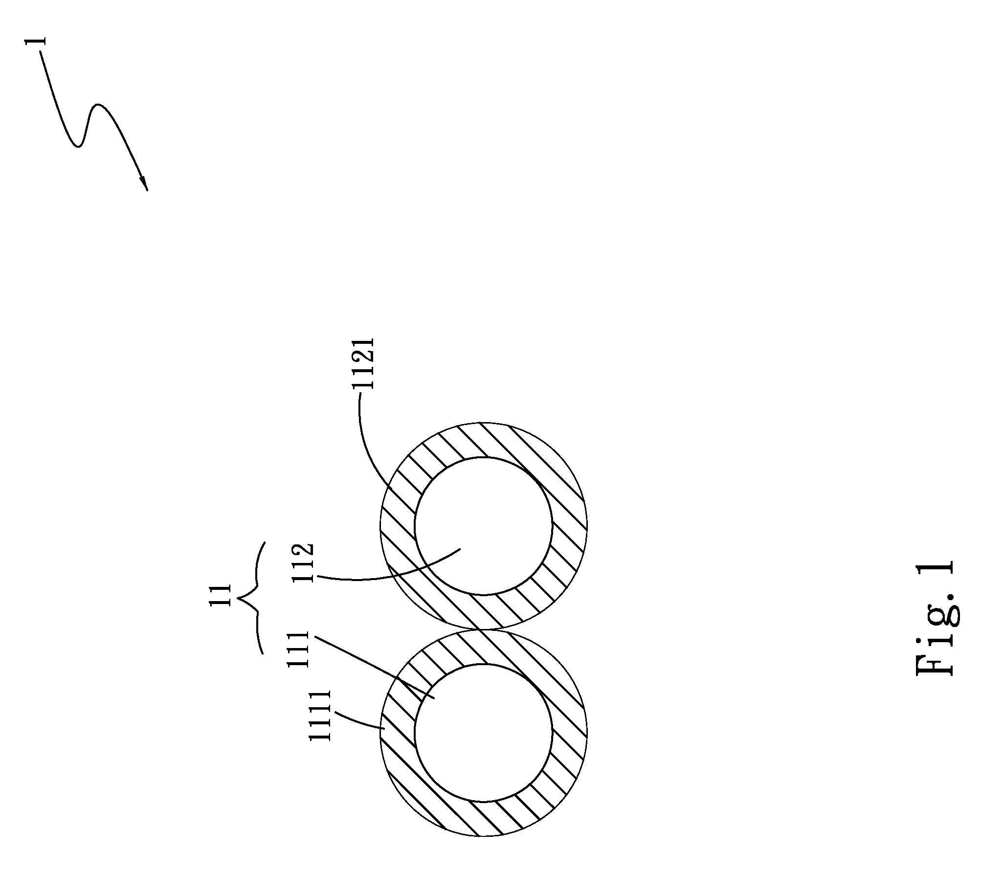
[0027]In the second embodiment, there is a difference between the dielectric values of the first sheath 1111 and the second sheath 1121. Since a high-dielectric material has good ability to concentrate electric field, the use of a low-dielectric material for one conductor in each of the signal pairs can reduce electric field concentration and accordingly, reduce crosstalk noise interference between the signal pairs.

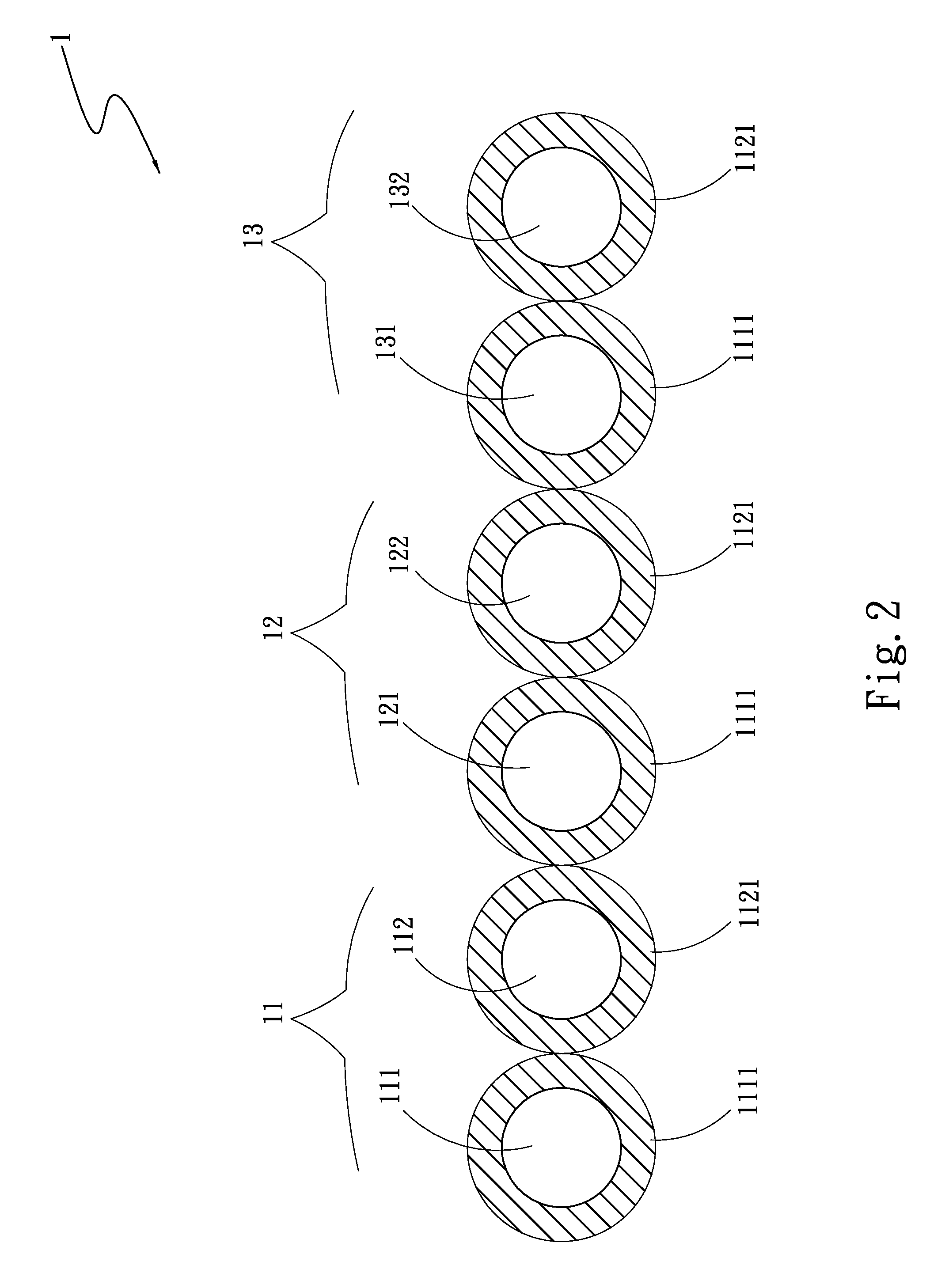
[0028]FIG. 3 is a cross sectional view of a transmission unit 1 according to a third embodiment of the present invention. As shown, in the third embodiment, the transmission unit 1 includes a first conductor group 11 having at least one first conductor 111 surrounded by a first sheath 1111 and at least one second conductor 112; a second conductor group 12 having at least one third conductor 121 surrounded by a first sheath 1111 and at least one fourth conductor 122; a third conductor group 13 having at least one fifth conductor 131 surrounded by a first sheath 1111 and at...

fourth embodiment

[0030]In the fourth embodiment, the transmission unit 1 includes differential signal pairs and earth conductors. There is a difference between the dielectric values of the first and second sheaths 1111, 1121 and the third sheath 1113. Since a high-dielectric material has good ability to concentrate electric field, the use of a low-dielectric material for one conductor in each of the signal pairs can reduce electric field concentration and accordingly, reduce crosstalk noise interference between the signal pairs.

[0031]FIG. 5 is a cross sectional view of a transmission unit 1 according to a fifth embodiment of the present invention. As shown, in the fifth embodiment, the transmission unit 1 includes a first conductor group 11 having at least one first conductor 111 surrounded by a first sheath 1111 and at least one second conductor 112 surrounded by a second sheath 1121; a second conductor group 12 having at least one third conductor 121 surrounded by a first sheath 1111 and at least ...

fifth embodiment

[0032]Alternatively, the transmission unit 1 in the fifth embodiment may include differential signal pairs without earth conductors. There are differences between the dielectric values of the first, the second and the third sheath 1111, 1121, 1113. Since a high-dielectric material has good ability to concentrate electric field, the use of a low-dielectric material for one conductor in each of the signal pairs can reduce electric field concentration and accordingly, reduce crosstalk noise interference between the signal pairs.

[0033]FIG. 6 is a cross sectional view of a transmission unit 1 according to a sixth embodiment of the present invention. As shown, in the sixth embodiment, the transmission unit 1 includes a first conductor group 11 having at least one first conductor 111 surrounded by a first sheath 1111 and at least one second conductor 112; and a second sheath 1121 surrounding the first sheath 1111 and the second conductor 112. The first and the second conductor 111, 112 are...


PUM


Abstract

A transmission unit with reduced crosstalk signal includes a first conductor group having at least one first conductor surrounded by a first sheath and at least one second conductor surrounded by a second sheath. The first and the second conductor are axially arranged corresponding to one another. The first sheath has a dielectric coefficient higher than that of the second sheath, so that a difference in dielectric property exists between the first and the second conductor to enable reduction of crosstalk occurred during high-speed signal transmission over the transmission unit.

Description

FIELD OF THE INVENTION[0001]The present invention relates to a transmission unit, and more particularly to a transmission unit that includes conductors surrounded by sheaths of different dielectric coefficients, so that a difference in dielectric property exists between the conductors to enable reduction of crosstalk occurred during high-speed signal transmission over the transmission unit.BACKGROUND OF THE INVENTION[0002]In recent years, the applications of audio and video signals have been constantly widened and improved. For example, video compact disk (VCD), digital versatile disk (DVD), high-definition digital television (HDTV), video call and video conference all have been introduced into people's daily life. Most of the currently available audio video (AV) systems process voice and image information in a completely digitalized manner to meet the newest technological trend. Different specifications and standards for AV systems have been constantly established, revised and upda...

Claims


Application Information

Patent Timeline
Patent Type & Authority Applications(United States)
IPC IPC(8): H04B3/28
CPCH04B3/28
Inventor LIU, DA-YULIU, DA-YUNGLIU, TENG-LANJANG, BEN-HWA
Owner YES WAY ENTERPRISE CORP
Why Eureka
Try Eureka