
Method and device for monitoring a turbine engine of an aircraft

a technology for aircraft and turbine engines, which is applied in the direction of machines/engines, efficient propulsion technologies, instruments, etc., can solve the problems of mechanical lock of the turbine, significant damage to the propulsive system, and cracks in the metal structure of the engine components,

Active Publication Date: 2014-12-23
AIRBUS OPERATIONS (SAS) +1
View PDF5 Cites 40 Cited by
  • Summary
  • Abstract
  • Description
  • Claims
  • Application Information

AI Technical Summary

Benefits of technology

The present invention provides a method to help aircraft crews monitor the condition of turbine engines on their aircraft. This method allows detection and indication of conditions that could lead to thermomechanical lock or difficulty starting the engine. By observing the information displayed, a crew member can quickly interpret the engine condition and take suitable decisions. This method also allows for the temporary shutdown of turbine engines on the ground, reducing mechanical stresses and increasing the life of the engine components. This results in cost savings and better engine performance.

Problems solved by technology

It is known that, under some operating conditions, the stoppage of a turbine engine such as a turbojet or a turbopropeller can result in a turbine mechanical lock, due to a differential expansion between stator and rotor elements.
When subjected to intensive and frequent thermal cycles, metal parts of the engine components actually undergo thermomechanical type stresses which may lead to cracks in the metal structure of the engine components.
Cracks initiated within the compressor or turbine disks for example can propagate and result in the breaking thereof.
The high speeds of rotation of these elements, as well as their big size, can result upon breaking thereof in significant damage to the propulsive system, to the aircraft or to the environment, because the energy level being induced is then very high.
In the case of the engine being stopped by an abrupt shutdown, for example caused by an aerodynamic distortion, a temporary fuel deprivation or on a crew command, the air used for cooling mechanic parts of the turbine does not flow any longer sufficiently within the engine.
Then, the differential expansion and contraction between the turbine rotor, stator and casing are such that these parts can come into mechanical contact and can make it impossible to re-start the windmilling engine, or even with the assistance of the starter.
If there is no contact and no rotation possible, re-starting an engine which has been shut down without waiting for a sufficiently long period at idle can result in vibrations or frictions at the end of the rotating parts, generated for example by a so-called “rotor bow” phenomenon where the shaft bearing the compressor stages and the turbine as well as the fixed structure consisting of the stators and the casing are bowed between the two ends thereof.
Starting under an excessive “rotor bow” and a contact with the compressor vanes can initiate cracks in the latter.

Method used


Image

  • Method and device for monitoring a turbine engine of an aircraft
  • Method and device for monitoring a turbine engine of an aircraft
  • Method and device for monitoring a turbine engine of an aircraft

Examples


first embodiment

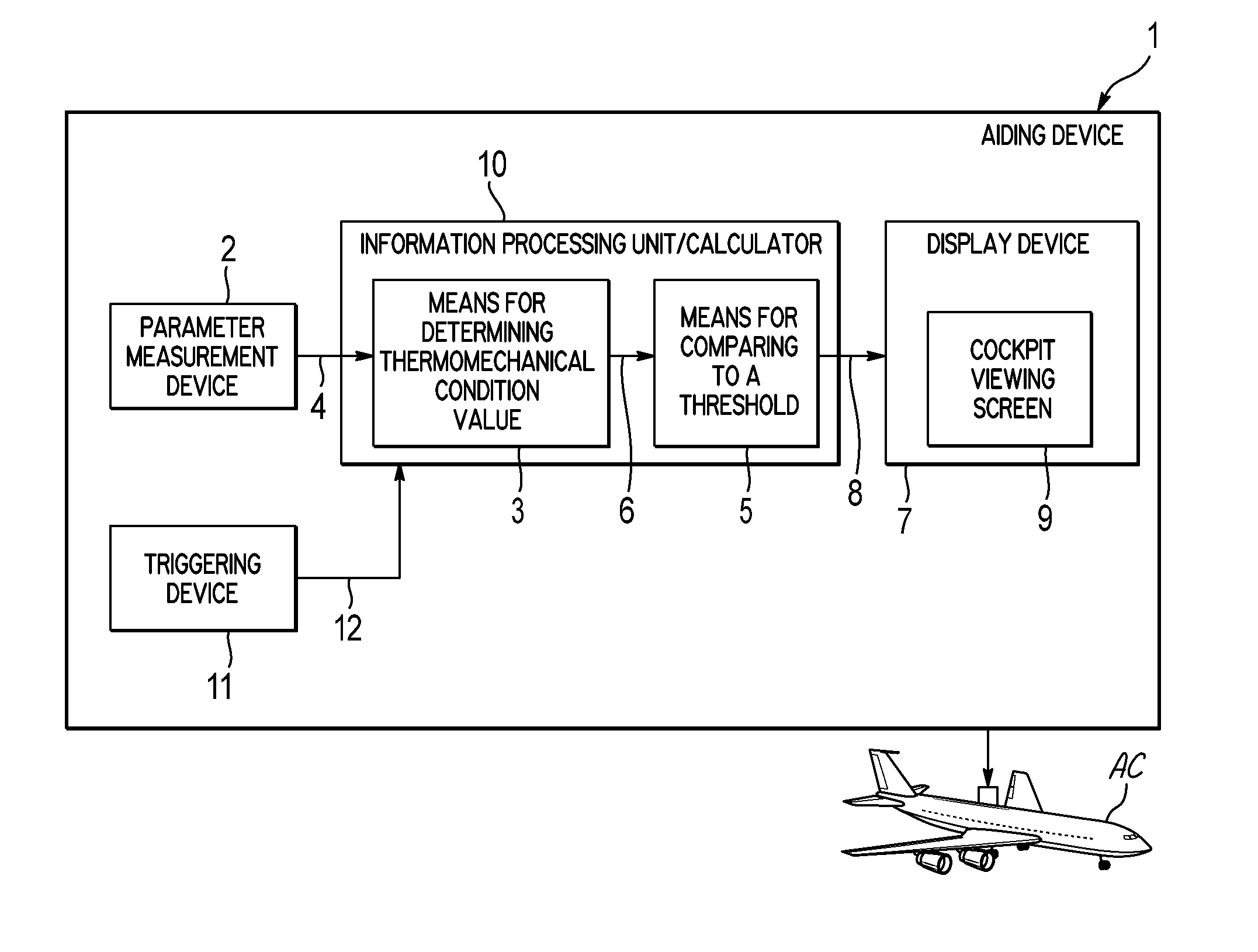
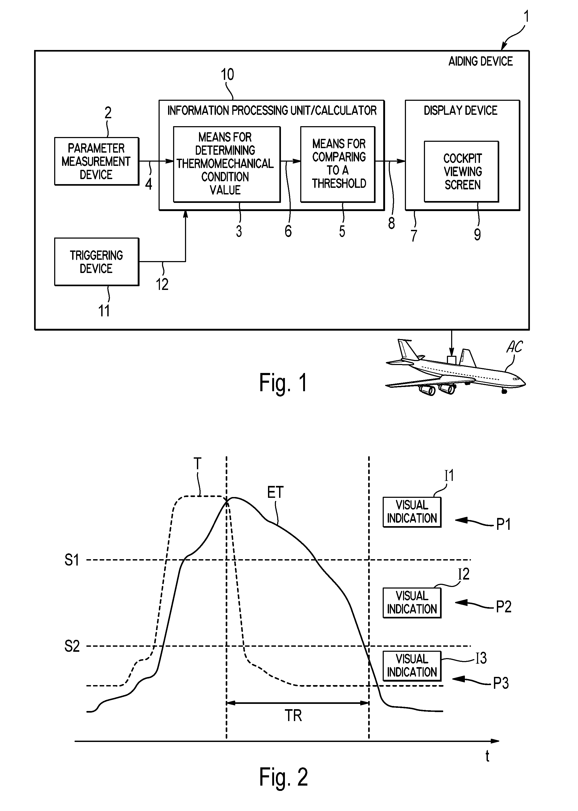
[0077]the invention is applied to an aircraft which is in a ground phase. In this case, when the turbine engine monitored is operating, the aiding device 1 shows on the screen 9 an indication indicating the risk involved in a case of a turbine engine shutdown (depending on the current thermomechanical condition calculated). Moreover, in this case, if a shutdown (whether wanted or not) of the turbine engine occurs, the aiding device 1 shows on the screen 9 an indication providing information relating to a possible turbine engine re-start. In particular, this indication can comprise a minimum waiting period being recommended before a re-start. Preferably, the screen 9 is a conventional screen which displays primary control parameters of the aircraft engines.

[0078]Thus, for an application on the ground, an indicator is provided within the cockpit which allows to indicate to the crew the risk involved in the case of an engine shutdown. This indication enables the shutdown of engines of ...

second embodiment

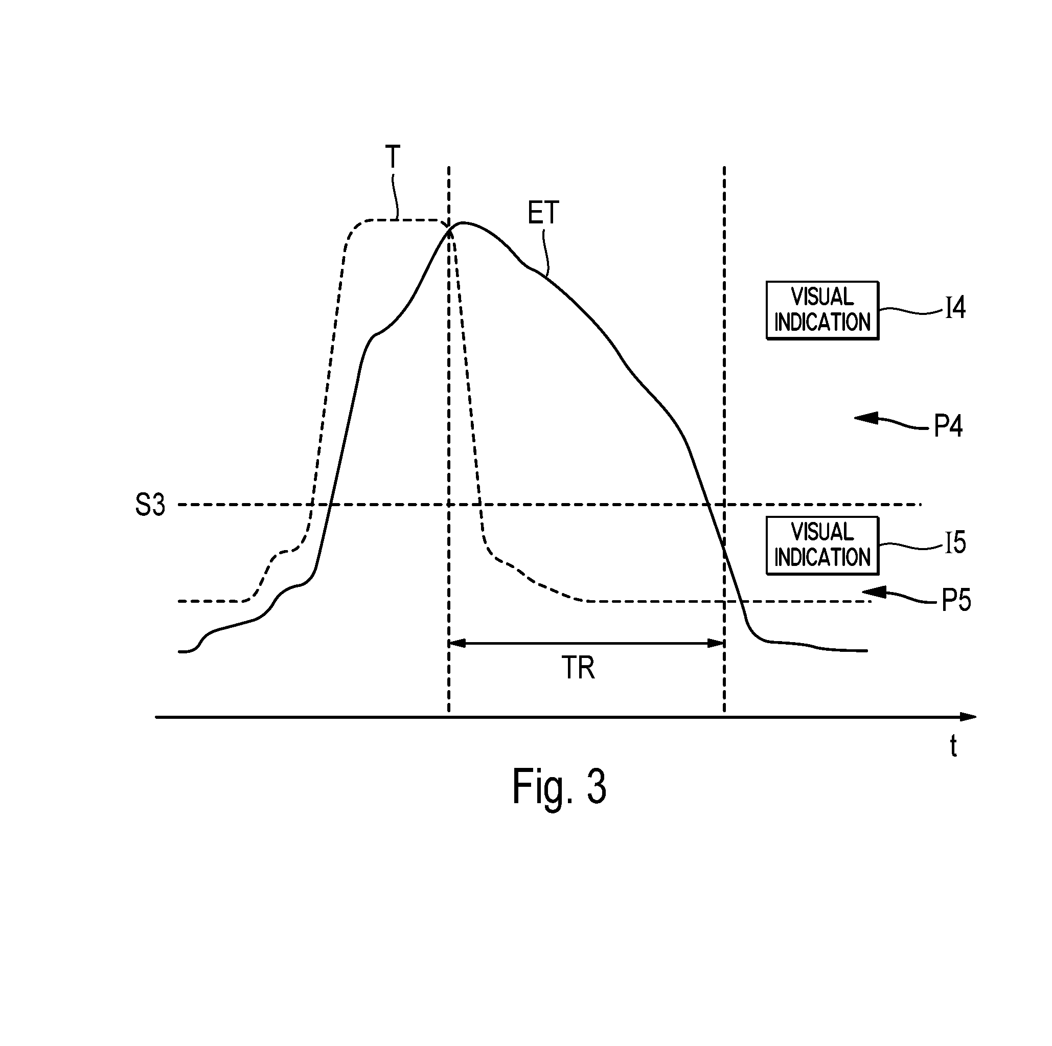
[0099]Furthermore, the invention is applied to an aircraft which is in a flight phase. In this case, if a shutdown (whether wanted or not) of the turbine engine occurs, the device 1 displays on the viewing screen 9 an indication I4, I5 which gives information about the operational piloting procedure to be followed in order to enable the engine to be re-started in optimum conditions. If necessary, such an indication can also indicate an optimum aircraft speed for the turbine engine in windmilling re-start.

[0100]In the embodiment described hereinafter (by way of example) in reference to FIG. 3, the means 5 compare the current value ETc (determined by means 3) of the thermomechanical condition ET to a single threshold value S3, and indications I4 and I5 displayed on the viewing screen 9 depend on the result of this comparison. In this case, the turbine engine can have one of the two following thermomechanical conditions P4 and P5:[0101]critical (P4), when the current value ETc is highe...


PUM


Abstract

A method and device aids in monitoring at least one turbine engine in an aircraft. The method includes determining a value illustrating a thermomechanical state of the turbine engine, and comparing the determined value with at least one threshold. The method also includes displaying in the cockpit of the aircraft, at least one indication related to the operation of the turbine engine, according to this comparison. As a result, conditions that could result in mechanical degradation or failure of the turbine engine are identified for a crew of the aircraft.

Description

TECHNICAL FIELD[0001]The present invention relates to an aiding method and device for monitoring a turbine engine of an aircraft, in particular a transport plane.[0002]The invention relates to detection and procedure processing of the differential heat expansion conditions that can result in a rotor lock or other mechanical degradations on engines of the aircraft turbine engine type, as well as to the improvement in procedures for shutting down and relighting such turbine engines.BACKGROUND[0003]It is known that, under some operating conditions, the stoppage of a turbine engine such as a turbojet or a turbopropeller can result in a turbine mechanical lock, due to a differential expansion between stator and rotor elements. This phenomenon is known as “core lock” or “rotor lock”. This lock makes it impossible to re-start the engine: upon a flight, in the case of an abrupt shutdown, but also on the ground, in the case of too an early shutdown after landing or for fuel saving purposes, ...

Claims


Application Information

Patent Timeline
Patent Type & Authority Patents(United States)
IPC IPC(8): F01D21/00F02C7/262G06F19/00F02C9/00
CPCY02T50/671F05D2270/092F05D2260/80F01D21/003F02C9/00F05D2270/303F05D2220/323F02C7/262Y02T50/60
Inventor JEGU, PATRICKBIRNFELD, MANFRED
Owner AIRBUS OPERATIONS (SAS)
Learn More