Rotationally symmetrical coherent verification phantom (virtual patient) with a flat detector disposed on a rotary axis integrated in a multi purpose QC-accessory

a qc-accessory and rotary axis technology, applied in the field of qc-accessory rotationally symmetrical coherent verification phantom (virtual patient) with a flat detector disposed on a rotary axis, can solve the problems of affecting sensitivity, limiting the number of detector elements suitable for measurement, and complicated methods, so as to achieve the effect of not losing accuracy

Inactive Publication Date: 2014-12-30
MOETTELI JOHN BRENT
View PDF2 Cites 11 Cited by
  • Summary
  • Abstract
  • Description
  • Claims
  • Application Information

AI Technical Summary

Benefits of technology

[0016]The symmetry axis of the RSC phantoms coincides with the gantry rotation axis. The 2D array is aligned to the isocenter line of the incident beam by turning the phantom around its symmetry axis, in order that the central beam impinges perpendicularly on the detector surface. The alignment of the phantom to the gantry can be achieved in different ways (see later). The favorable and most simple method is realized when the phantom is mounted on the gantry with a dedicated accessory system; with the same fixation technique as applied for the block tray accessory (photon beams) or the electron tube accessory (electron beams). The flexibility can be realized by switching the accessory coding system. Alternatively, the linac software provides an accessory code for photon as well as for electron beams.
[0026]These measurements are supported independent of the gantry and collimator angles without loss of accuracy. The novel concept of an accessory based combination of 3D plan verification and machine checks is a feature of the invention.

Problems solved by technology

These methods are quite elaborate and time-consuming and therefore not suitable for clinical routine: First of all, the 2D measurement signal has to be converted digitally (e.g., film scanning).
The beam impinges on the detectors partly at small angles, influencing the sensitivity in an adverse way, and limiting the number of detector elements suitable for measurements.
Therefore, detectors at the peripheries of the phantom are only suitable for measurements when the sensitivity is angle corrected (FIG. 1B), which introduces an additional measurement error.
A considerable percentage of the detectors thus cannot be used for the measurement without restrictions at a given gantry angle.
Since the measurement is performed distant to the isocenter plane, complex calculation algorithms are required to calculate the dose in a virtual 3D phantom.
Due to the phantom construction of the presented 3D verification phantoms and the limited accuracy to place them in relation to the beam coordinate system, the 3D phantoms actually in use are not suitable to perform fast and accurate machine checks, especially for MLC checks (multi leaf collimator).
Nevertheless, Häring et al's efforts highlighted problems in calculating the dose distribution, particularly, next to the phantom surface.
Cylindrical phantom shapes are therefore not suitable to verify techniques with varying collimator or table angles, when they are fixed to the gantry.

Method used


Image

  • Rotationally symmetrical coherent verification phantom (virtual patient) with a flat detector disposed on a rotary axis integrated in a multi purpose QC-accessory
  • Rotationally symmetrical coherent verification phantom (virtual patient) with a flat detector disposed on a rotary axis integrated in a multi purpose QC-accessory
  • Rotationally symmetrical coherent verification phantom (virtual patient) with a flat detector disposed on a rotary axis integrated in a multi purpose QC-accessory

Examples


Embodiment Construction

)

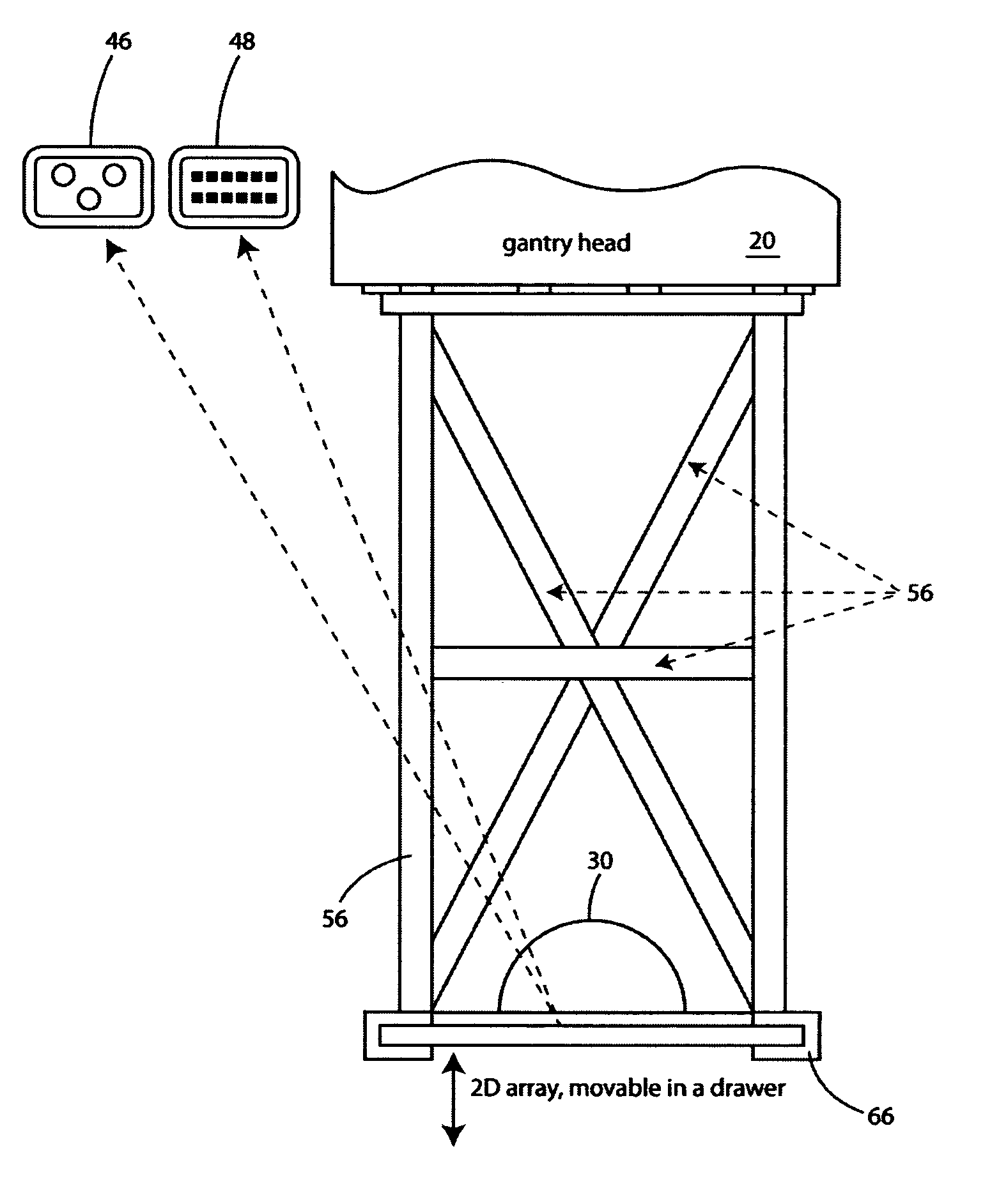
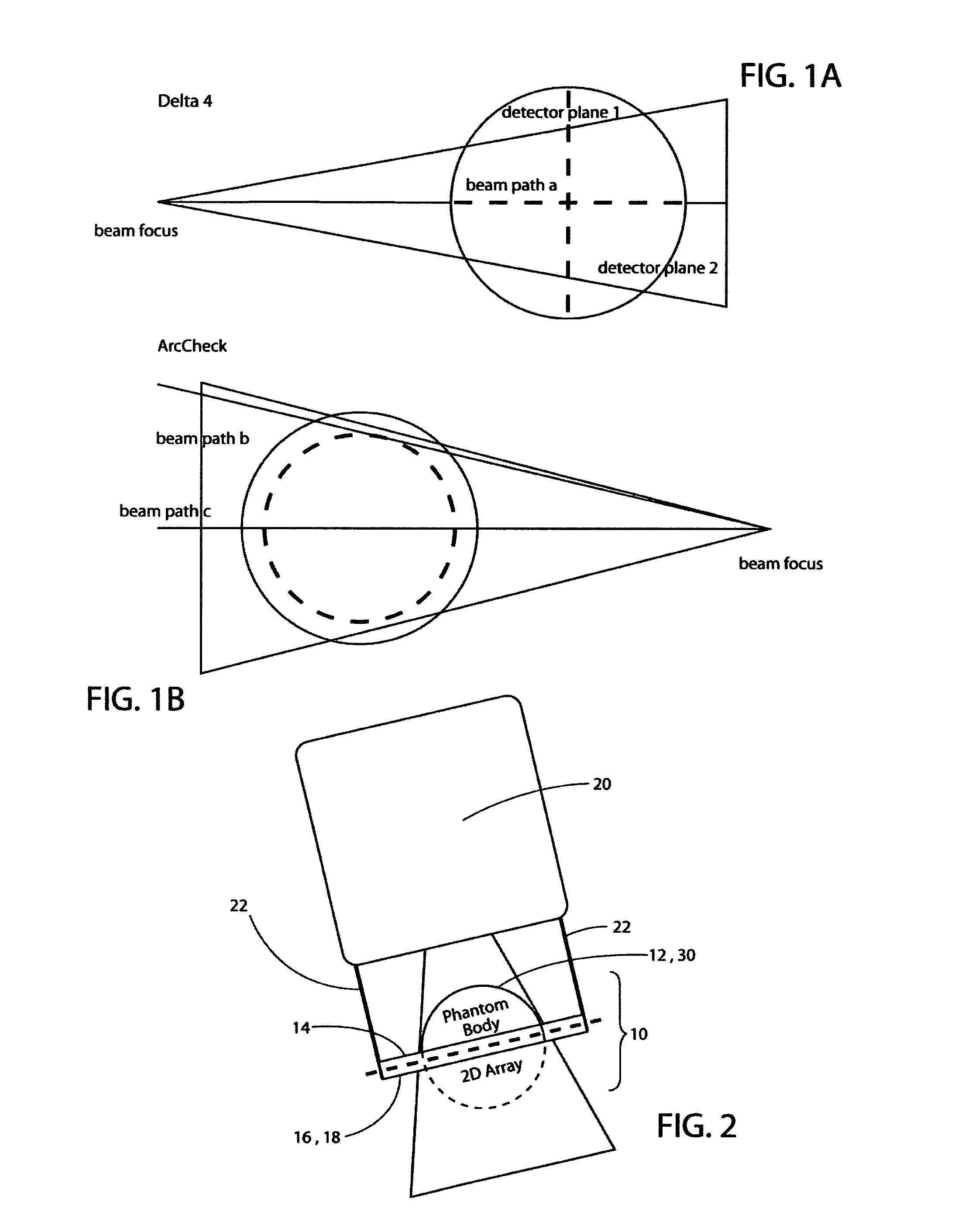
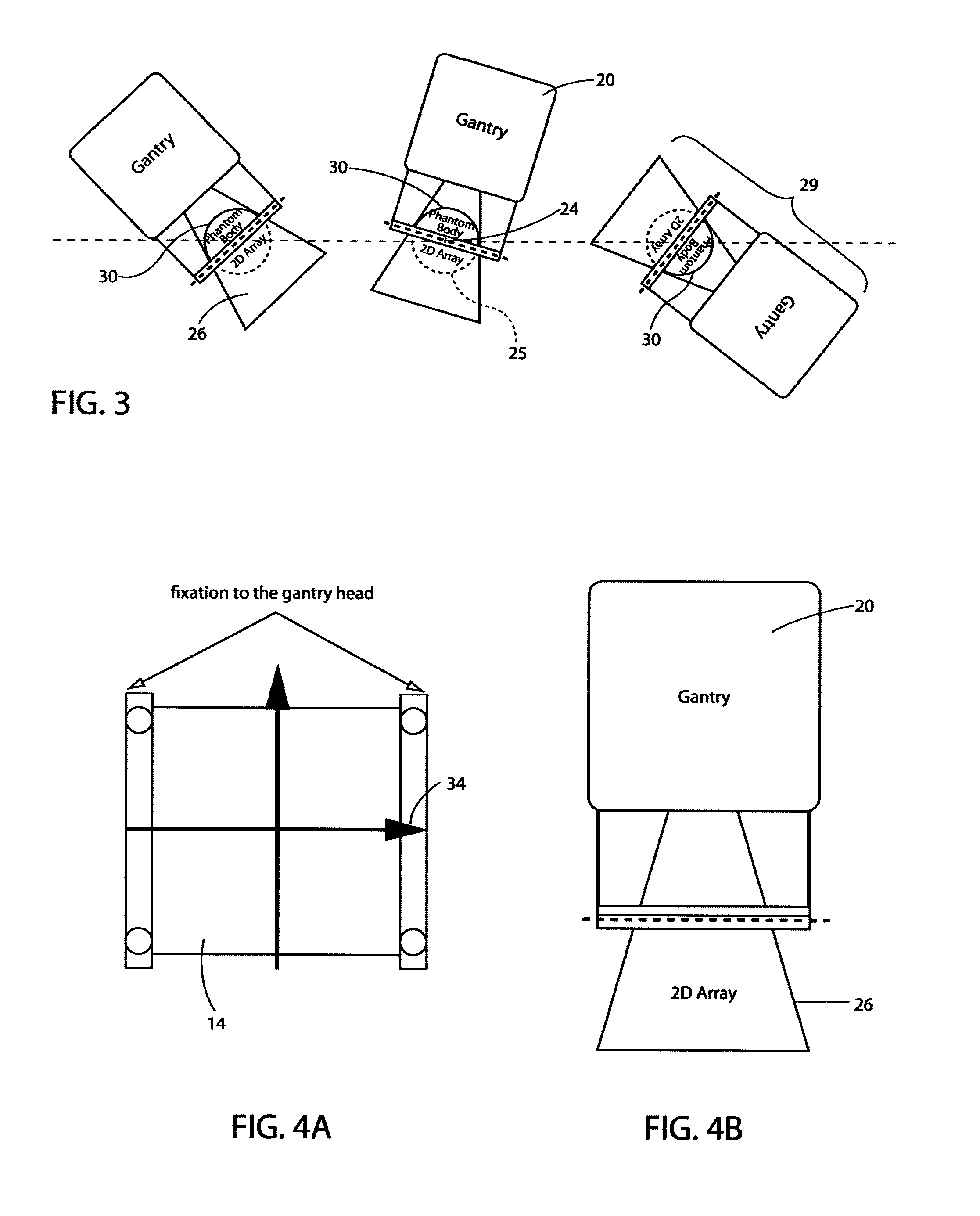
[0059]The QC accessory 10 (quality control accessory) consists in principal of three components: The gantry fixation accessory holder, the phantom body 30 or absorber 12, and the 2D array 14. Software is needed to interpret the measurement.

[0060]Referring now to FIG. 2, components of the QC accessory 10 are shown used in verification of 3D dose distribution. The QC accessory 10 includes an absorber 12 (in this case, a phantom 12, 32), and a 2d array 14 which is adapted to be fixed on a table 16 or collimator 18 which is held in a fixed spatial relationship to the gantry 20 by an orientation device 22 (in this case, a rigid structure).

Verification Phantom Component of the QC Accessory

[0061]The plan verification phantom as part of a general class of 3D phantoms is the most important component of the QC accessory 10. Members of the class of phantoms of the invention are called “Rotationally Symmetrical Coherent” phantoms (RSC phantoms). As indicated by the name, RSC phantoms are rotat...


PUM


Abstract

A quality control accessory (QC accessory) is provided which is adapted for use in linear accelerator quality control or in verification of an arbitrary isocentric radiation treatment plan of a patient or radiation sensitive body. The accessory includes an absorber, a detector and an optional orientation device. The absorber is rotationally symmetric, preferably spherical or hemispherical. The detector is adapted to be fixed in a stationary spatial relationship with respect to the absorber. The optional orientation device is adapted to maintain the two dimensional detector (2d detector) and the absorber in a fixed relative spatial relationship with respect to the beam focus of the linear accelerator, when the gantry is rotated, so that the central axis of the beam is essentially orthogonal to the 2d detector and the phantom axis of symmetry is parallel to or aligned with the central axis of the gantry rotation axis.

Description

CROSS REFERENCE TO RELATED APPLICATIONS[0001]This application is the National Stage of International Application No. PCT / IB2011 / 000224, filed Feb. 9, 2011, which claims benefit under 35 USC §119(a), to provisional US patent application Ser. No. 61 / 302,550 filed Feb. 9, 2010, provisional U.S. patent application Ser. No. 61 / 412,407, filed Nov. 11, 2010 and provisional U.S. patent application Ser. No. 61 / 418,439, filed Dec. 1, 2010.COPYRIGHT & LEGAL NOTICE[0002]A portion of the disclosure of this patent document contains material which is subject to copyright protection. The copyright owner has no objection to the facsimile reproduction by anyone of the patent document or the patent disclosure as it appears in the Patent and Trademark Office patent file or records, but otherwise reserves all copyright rights whatsoever. Further, no references to third party patents or articles made herein is to be construed as an admission that the present Invention is not entitled to antedate such mat...

Claims


Application Information

Patent Timeline
Patent Type & Authority Patents(United States)
IPC IPC(8): H04N5/33A61B18/20A61N5/10
CPCA61N5/1048A61N5/1075A61N2005/1076A61N2005/1095
Inventor SCHIEFER, HANS
Owner MOETTELI JOHN BRENT
Why Eureka
Try Eureka