Flexible, abrasion resistant textile sleeve and method of construction thereof

a technology of textile sleeves and sleeve walls, which is applied in the field of textile sleeves, can solve the problems of kinking and opening along the wrapped edges, requiring an increased volume of space, and the prior art wrappable sleeves can prove problematic in some applications, and achieve the effects of enhancing the curl-strength of the sleeve wall

Active Publication Date: 2015-01-06
FEDERAL MOGUL POWERTAIN LLC
View PDF24 Cites 19 Cited by
  • Summary
  • Abstract
  • Description
  • Claims
  • Application Information

AI Technical Summary

Benefits of technology

[0006]One aspect of the invention provides a woven sleeve for routing and protecting elongate members from exposure to abrasion and other environmental conditions, such as contamination. The sleeve has a flexible, abrasion resistant, self-curling elongate wall constructed from woven monofilament and multifilament yarns. The wall has opposite edges extending parallel to a central axis of the sleeve. The wall is woven with warp yarns extending parallel to the central axis and fill yarns extending transverse to the warp yarns. The warp yarns are provided at least in part as first monofilament yarns and the fill yarns are provided as second monofilament yarns and second multifilament yarns. The second monofilament yarns have a larger diameter than the first monofilament yarns, thereby enhancing the closing force of the heat-formed wall.
[0007]In accordance with another aspect of the invention, the warp yarns further include first multifilament yarns that extend over an edge region adjacent the opposite edges to assist in preventing the opposite edges from opening when the sleeve is bent around a corner, wherein the first monofilament yarns extend over an intermediate region between the edge regions to provide enhanced resistance to abrasion, with the edge regions being free of the first monofilament yarns, further enhancing the ability of the sleeve wall to remain in its intended heat-formed wrapped configuration.
[0008]In accordance with another aspect of the invention, a woven sleeve for routing and protecting elongate members from exposure to abrasion and other environmental conditions, such as contamination, is provided. The sleeve has an elongate wall having opposite edges extending parallel to a central axis of the sleeve. The wall is woven with warp yarns extending parallel to the central axis and fill yarns extending transverse to the warp yarns. The warp yarns are provided as first monofilament yarns and first multifilament yarns and the fill yarns are provided as second monofilament yarns and second multifilament yarns. The first multifilament yarns extend over an edge region adjacent the opposite edges to assist in maintaining the opposite edges in their intended overlapping relation when the sleeve is bent around a corner and the first monofilament yarns extending over an intermediate region between the edge regions. The edge regions are free of the first monofilament yarns and the intermediate region is free of the first multifilament yarns.

Problems solved by technology

Unfortunately, although the aforementioned multilayer sleeves may provide suitable protection against the various environmental conditions, they are typically bulky, thereby requiring an increased volume of space, being relatively heavy and exhibiting limited flexibility, thereby being subject to kinking and opening along wrapped edges.
Accordingly, wrappable sleeves constructed in accordance with the prior art can prove problematic in some applications, particularly applications requiring routing through tight, winding areas, and applications having weight restrictions, such as aircraft and aerospace applications, for example.

Method used


Image

  • Flexible, abrasion resistant textile sleeve and method of construction thereof
  • Flexible, abrasion resistant textile sleeve and method of construction thereof
  • Flexible, abrasion resistant textile sleeve and method of construction thereof

Examples


Embodiment Construction

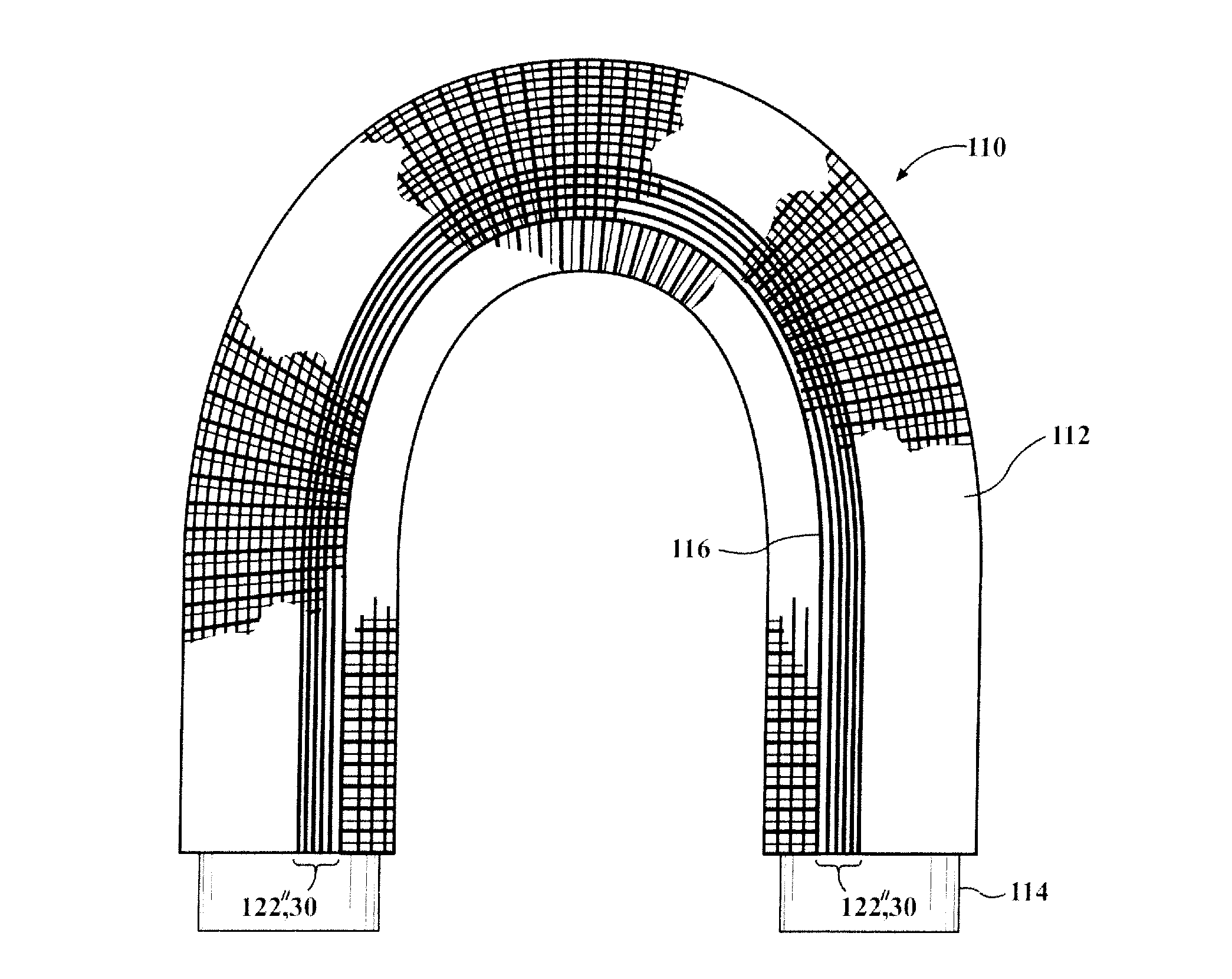
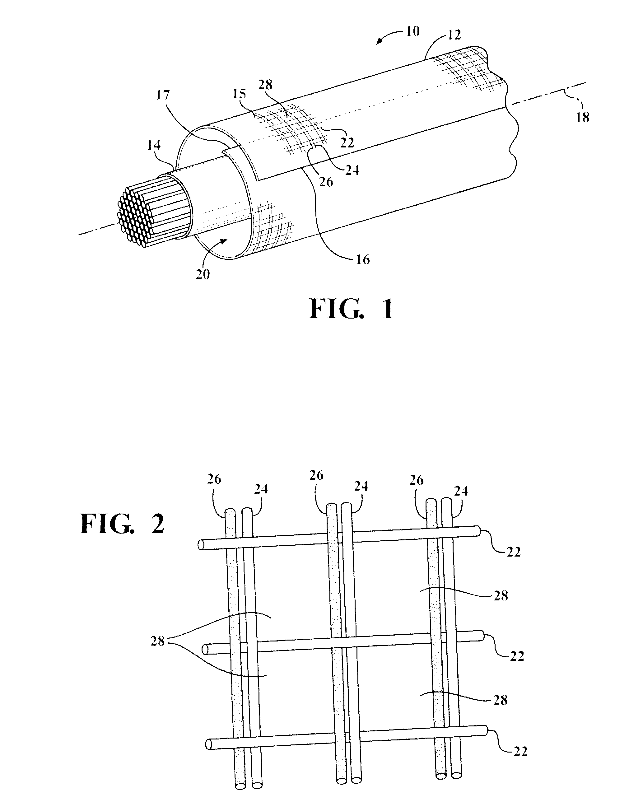
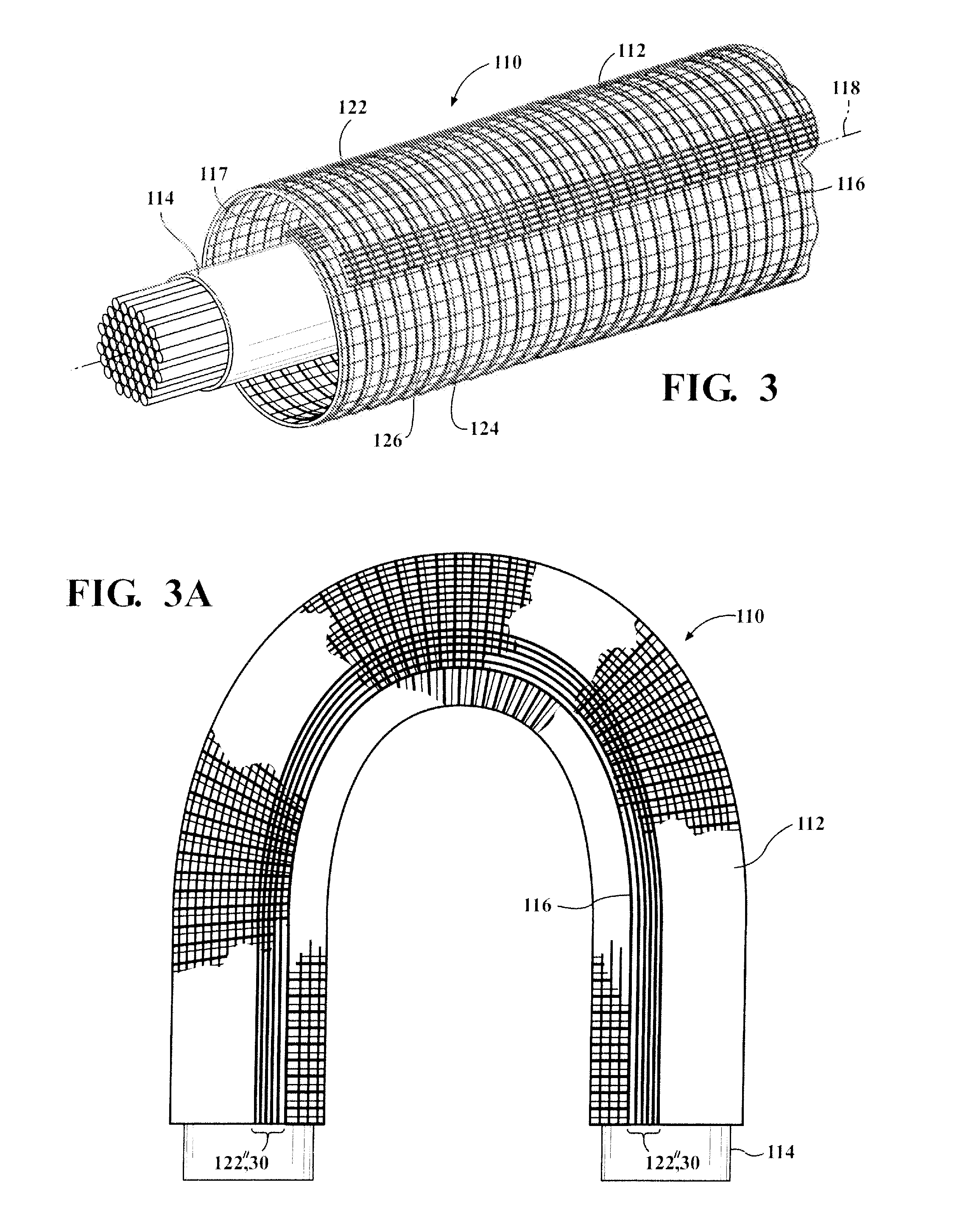
[0024]Referring in more detail to the drawings, FIG. 1 shows schematic representation of a woven, self-wrapping textile sleeve, referred to hereafter as sleeve 10, constructed in accordance with one aspect of the invention. The sleeve 10 has a self-wrapping elongate wall 12 for routing and protecting elongate members, such as wires or a wire harness 14, for example, from exposure to abrasion and the ingress of contamination, debris and the like. The elongate wall 12 has opposite edges 16, 17 extending generally parallel to a central, longitudinal axis 18, wherein the edges 16, 17 are preferably biased into overlapping relation with one another in “cigarette wrapped” fashion to fully enclose the elongate members 14 within a central cavity 20 of the sleeve. The cavity 20 is readily accessible along the full length of the longitudinal axis 18 so that the elongate members 14 can be readily disposed radially into the cavity 20, and conversely, removed from the cavity 20, such as during s...


PUM

PropertyMeasurementUnit
diameteraaaaaaaaaa
widthaaaaaaaaaa
wall thicknessaaaaaaaaaa

Abstract

A textile sleeve for routing and protecting elongate members and method of construction thereof is provided. The sleeve includes an elongate wall having opposite edges extending parallel to a central axis of the sleeve. The wall is woven with warp yarns extending parallel to the axis and fill yarns extending transverse to the warp yarns. The warp yarns include monofilament yarns within an intermediate region of the wall and multifilament yarns within opposite edge regions of the wall to enhance abrasion resistance and curl, respectively, and the fill yarns include monofilament yarns larger in diameter than the fill monofilament yarns to provide further abrasion resistance, enhanced curl strength and multifilament yarns to provide increased coverage, maintain flexibility, and to maintain the warp monofilaments in their intended position.

Description

CROSS-REFERENCE TO RELATED APPLICATION[0001]This application is a continuation-in-part of U.S. application Ser. No. 12 / 797,798, filed Jun. 6, 2010, which claims the benefit of U.S. Provisional Application Ser. No. 61 / 186,174, filed Jun. 11, 2009, both of which are incorporated herein by reference in its entirety.BACKGROUND OF THE INVENTION[0002]1. Technical Field[0003]This invention relates generally to textile sleeves for protecting elongate members, and more particularly to woven sleeves.[0004]2. Related Art[0005]It is known to wrap wires and wire harnesses in protective sleeves, such as in automobiles, aircraft or aerospace craft, to provide protection to the wires against abrasion, fluid and thermal affects. In order to achieve the desired protection, the protective sleeve may have multiple layers, with some of the layers being specifically provided for different types of protection. For example, one layer may be provided for water resistance, e.g. a sheet of plastic material, w...

Claims


Application Information

Patent Timeline
Patent Type & Authority Patents(United States)
IPC IPC(8): D03D3/02D03D1/00D03D23/00D03D25/00B60R16/02D03D3/08D03D15/00H02G3/04
CPCD03D3/02B60R16/0215D03D1/0041D03D3/08D03D15/00B60R16/02H02G3/0481D10B2331/04D10B2331/301D10B2401/04D03D1/0043D03D15/283D06C7/02
Inventor ITOH, EMI
Owner FEDERAL MOGUL POWERTAIN LLC
Why Eureka
Try Eureka