CMC turbine stator blade

a technology of stator blades and turbines, which is applied in the direction of wind motors with parallel air flow, wind motors with perpendicular air flow, liquid fuel engine components, etc., can solve the problems of high manufacturing cost, loss of thrust force, and difficulty in integrally forming blades and fiber fabrics using the current technique, so as to reduce the concentration of stress and reduce the leakage of gas

Active Publication Date: 2015-01-06
IHI CORP
View PDF12 Cites 25 Cited by
  • Summary
  • Abstract
  • Description
  • Claims
  • Application Information

AI Technical Summary

Benefits of technology

[0024]According to the CMC turbine stator blade of the present invention, it is possible to reduce a concentration of stress in the bonded portion between the blade and the band, reduce the leakage of a gas between the blade and the band, and simply fasten the blade and the band to each other during assembly.

Problems solved by technology

Since the turbine stator blade has a complex structure to perform such film cooling, manufacturing costs become high.
Further, since a part of high-pressure air contributing to the thrust force is used as cooling air, there is a loss in the thrust force.
For this reason, it is difficult to integrally form the portions of the blade and the band from the fiber fabric using the current technique.
Further, in the case where a gap is formed in the fastened portion, the mainstream gas may leak from the gap.

Method used


Image

  • CMC turbine stator blade
  • CMC turbine stator blade
  • CMC turbine stator blade

Examples


first embodiment

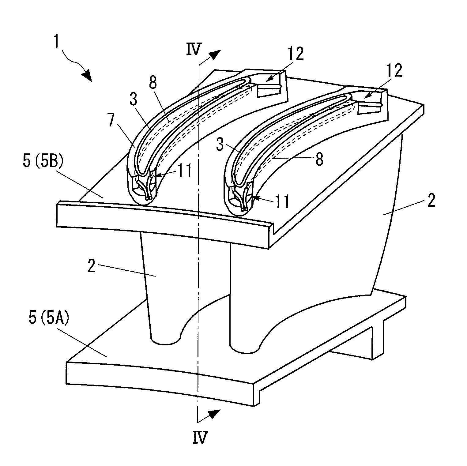
[0035]FIG. 3 is a diagram illustrating a turbine stator blade 1 according to the present invention, and is a schematic perspective view when the turbine stator blade 1 is seen from the upstream side of the flow direction of the mainstream gas.

[0036]In the description below, the “radial direction” indicates the radial direction of the turbine.

[0037]In FIG. 3, the CMC turbine stator blade 1 includes a plurality of blades 2 which are disposed at intervals in the circumferential direction about the axis of the turbine, and bands 5 which support both ends of each blade 2 and extend in the circumferential direction. In the specification, the band 5 located at the inner side (the lower side of FIG. 3) of the radial direction is defined as a first band 5A, and the band 5 located at the outer side (the upper side of FIG. 3) of the radial direction is defined as a second band 5B. However, hereinafter, both the first band 5A and the second band 5B are generally referred to as the band 5 except...

second embodiment

[0064]Further, in the second embodiment, since the adhering member 13 is also used, it is possible to reinforce the fixing between the blade 2 and the band 5, and more securely fasten the blade 2 and the band 5 to each other. Further, by using the flexible adhesive, it is possible to further reduce a concentration of stress.

[0065]Furthermore, although the embodiments of the present invention have been described, the above-described embodiments of the present invention are merely examples, and the scope of the present invention is not limited thereto. The scope of the present invention is shown in the claims, and includes all modifications within the concept and the scope equivalent to those of the claims.


PUM


Abstract

A CMC turbine stator blade 1 includes a blade 2 of a ceramic matrix composite material formed or a metallic material, and a band 5 formed of a ceramic matrix composite material and supporting the blade 2. The blade 2 includes a first fitting portion 3 to which the band 5 is fitted outside. The band 5 includes a second fitting portion 7 to which the first fitting portion 3 is fitted inside. A flexible wire 8 is disposed between the fitting portions 3, 7 to fix the blade 2 and the band 5. A first groove 3a in the outer peripheral surface of the first fitting portion 3 extends in the front-to-rear direction of the blade 2. A second groove 7a in the inner peripheral surface of the second fitting portion 7a extends along the first groove 3a. The wire 8 is disposed between the grooves 3a,7a.

Description

[0001]This is a National Phase Application in the United States of International Patent Application No. PCT / JP2010 / 055104 filed Mar. 24, 2010, which claims priority on Japanese Patent Application No. 2009-075962, filed Mar. 26, 2009. The entire disclosures of the above patent applications are hereby incorporated by reference.TECHNICAL FIELD[0002]The present invention relates to a turbine blade that is formed of a ceramic matrix composite material (CMC), and particularly, to a CMC turbine stator blade in which a blade and a band are fastened (bonded) to each other with a simple structure.BACKGROUND ART[0003]A turbine stator blade is a component arranged in a flow path of a combustion gas from a combustor in a gas turbine engine. FIG. 1 illustrates an example of an existing turbine blade 30. The turbine blade 30 includes a plurality of blades 31 which are disposed about the axis of the turbine at intervals in the circumferential direction, and bands 32 which support both ends of each ...

Claims


Application Information

Patent Timeline
Patent Type & Authority Patents(United States)
IPC IPC(8): F01D9/04F01D5/28F01D11/00F16J15/06
CPCF01D5/282F01D5/284F01D9/042F01D11/005F16J15/062Y02T50/672F05D2300/603Y02T50/60
Inventor TANAHASHI, YOSUKETAKAHASHI, AKIRAYAGI, HIROYUKI
Owner IHI CORP
Why Eureka
Try Eureka