Device for shaping materials using induction heating that enables preheating of the device

Inactive Publication Date: 2015-01-06
ROCTOOL SAS
View PDF8 Cites 3 Cited by
  • Summary
  • Abstract
  • Description
  • Claims
  • Application Information

AI Technical Summary

Benefits of technology

The patent describes a mold that allows for shorter heating and cooling times, which improves the flow of material during molding. The mold uses magnetic fields to induce currents at the surface of the molding zones, which can be controlled to preheat the mold and aid in the filling of the mold. Overall, this technology improves the efficiency and quality of the molding process.

Problems solved by technology

An induction heating device as mentioned above allows very short heating / cooling cycles, but its use for molding a material such as L.F.T. seems inappropriate.
Indeed, the need to provide a compression chamber with a satisfactory sealing is hardly compatible with the technology of this type of device, which requires the two sides of the mold to be electrically insulated so that it is heated.

Method used


Image

  • Device for shaping materials using induction heating that enables preheating of the device
  • Device for shaping materials using induction heating that enables preheating of the device
  • Device for shaping materials using induction heating that enables preheating of the device

Examples


Embodiment Construction

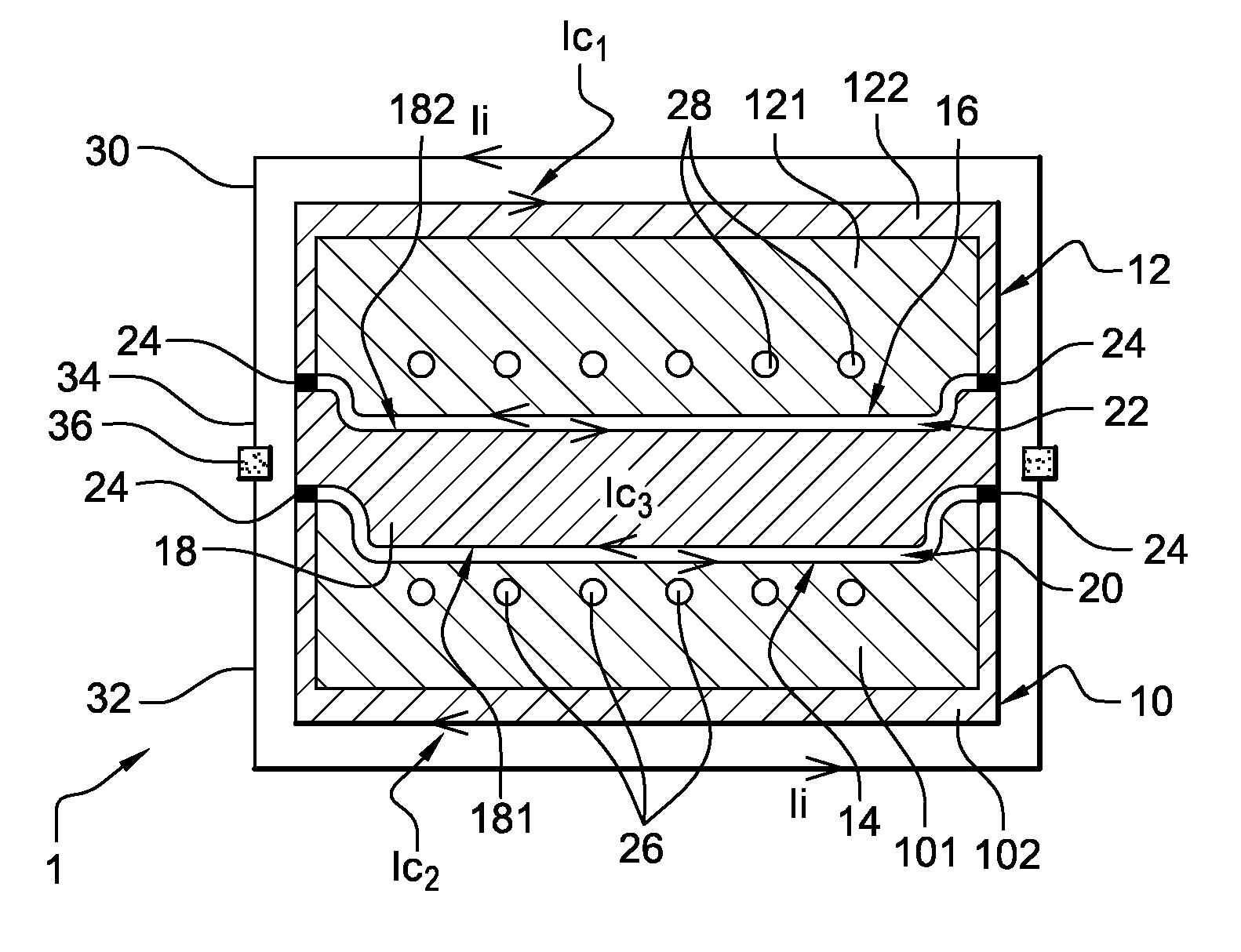
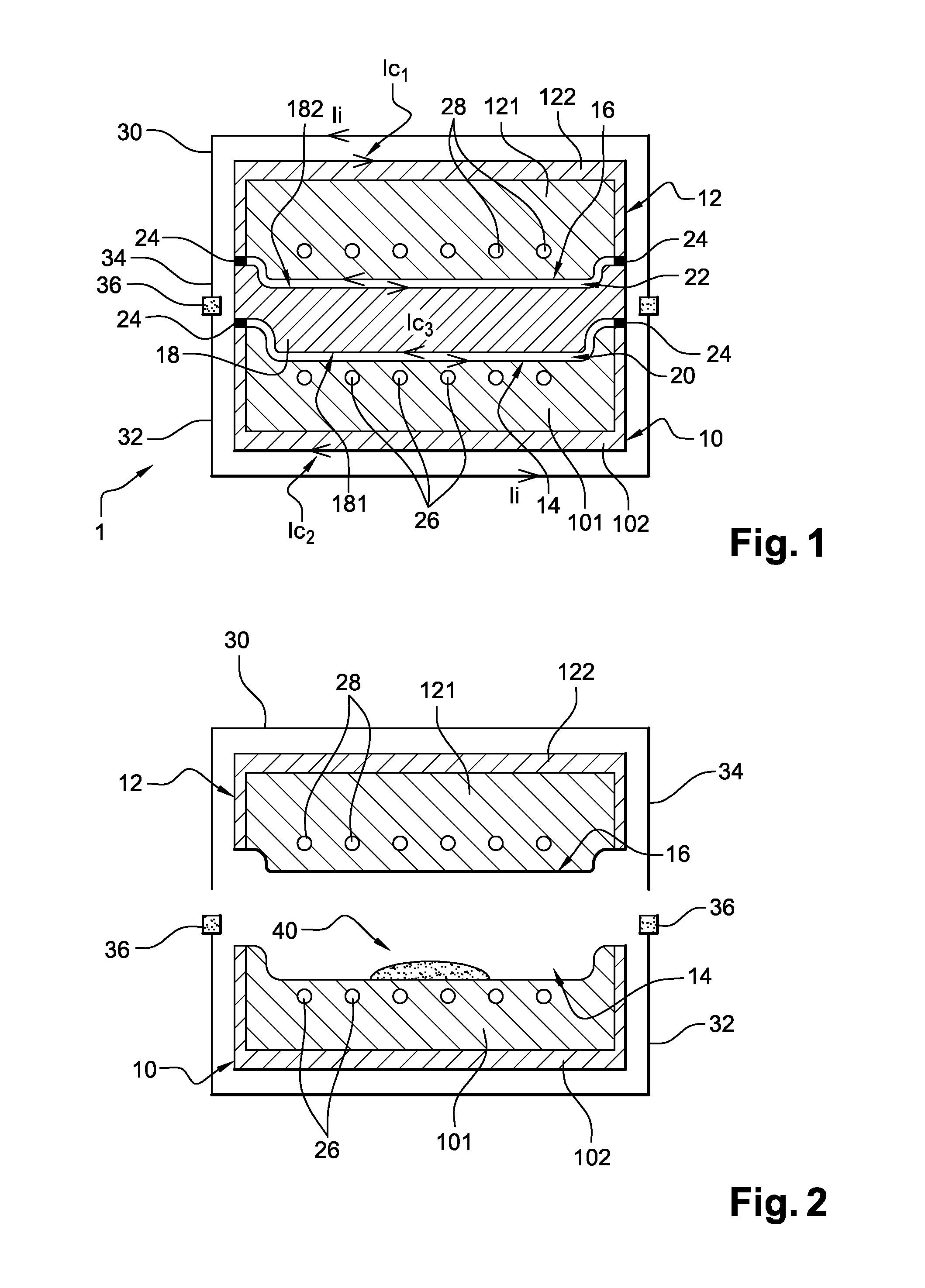
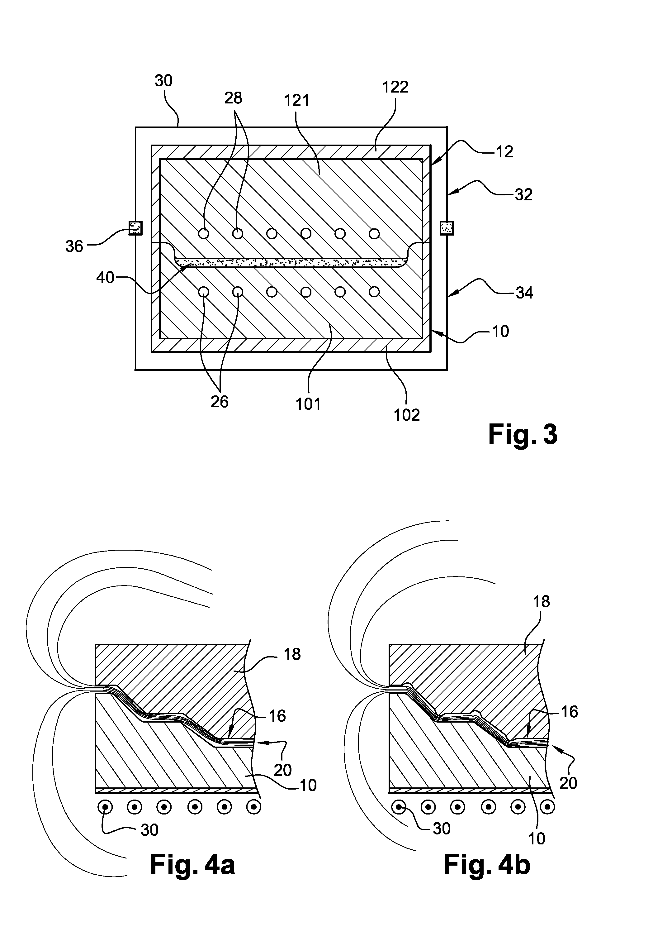
[0051]The device 1 shown in FIGS. 1-3, comprises two mold bodies, a lower mold body, or die 10, and an upper mold body, or punch 12. Both are made of an electrically conductive material, and they each comprise a portion constituting a heating zone, or molding zone, respectively 14 for the die 10 and 16 for the punch 12. The two mold bodies 10, 12 are able to come into contact with each other to achieve the molding of a piece, the molding zones 14, 16, arranged face-to-face, thus forming a closed chamber, for instance a compression chamber.

[0052]A network of inductors 30, electrically connected in parallel or in serial connection and connected to a power generator, is placed around the assembly formed by the die 10 and the punch 12. Each inductor 30 comprises a conductive turn and includes two separable portions 32, 34. The lower portion 32 is secured to the die 10 while the upper portion 34 is secured to the punch 12.

[0053]In accordance with the invention, to allow preheating of dev...


PUM

PropertyMeasurementUnit
Frequencyaaaaaaaaaa
Frequencyaaaaaaaaaa
Magnetic fieldaaaaaaaaaa

Abstract

A molding device for the shaping of a material includes:a lower mold body, or die, made from an electrically conductive material and including a molding zone intended to be in contact with the material to be shaped;an upper mold body, or punch, made from an electrically conductive material, and including a molding zone intended to be in contact with the material to shaped;a removable intermediate part, or core, made of an electrically conductive material, and intended to be inserted between the die and the punch;induction elements for generating a magnetic field that surrounds the die, the punch and the intermediate part; these three components being electrically insulated in pairs, so that the opposite faces of the intermediate part and the die, and those of the intermediate part and the punch, delimit two air gaps in which the magnetic field flows which induces currents at the surface of the molding zones of the die and the punch, thus making it possible to localize the action of the inductors at the surface of the molding zones.

Description

[0001]The present invention relates to a device and a method using induction heating in order to carry out the shaping, particularly by molding, of materials, in particular thermoplastic or thermosetting matrix composite materials.BACKGROUND OF THE INVENTION[0002]A device is known, such as that described in international patent application no. WO2005 / 094127, which makes it possible to localize the induction heating, so as to delimit the heating at the mold / material interface.[0003]Such a device comprises inductors surrounding two electrically conductive mold bodies and comprising a heating zone intended to be in contact with the material to be shaped, the mold bodies being electrically insulated from each other. Thus, thanks to this electrical disconnection between the two mold bodies, the opposite faces of these latter delimit an air gap through which the magnetic field created by the inductors flows. The magnetic field thus induces electrical currents on the surface of the mold bo...

Claims


Application Information

Patent Timeline
IPC IPC(8): B29C35/02B29C33/06B29C33/08B29C35/08B29C43/52H05B6/10
CPCB29C33/06B29C35/0805B29C43/52H05B6/105B29C33/08B29C2035/0811
Inventor GUICHARD, ALEXANDREFEIGENBLUM, JOSE
Owner ROCTOOL SAS
Why Eureka
Try Eureka