Automatic optical detection system based on CPU+GPU+FPGA architecture

A technology of automatic optical detection and optical fiber interface, which is applied in the field of automatic optical detection system based on CPU+GPU+FPGA architecture, can solve the problems of lack of scalability, limited number of acquisition cards, and failure to achieve expected results, and achieves improved performance. The effect of image processing computing power, fast data transmission speed, and strong computing processing power

Active Publication Date: 2018-03-20
WUHAN JINGCE ELECTRONICS GRP CO LTD
View PDF6 Cites 15 Cited by
  • Summary
  • Abstract
  • Description
  • Claims
  • Application Information

AI Technical Summary

Problems solved by technology

Therefore, this simple system integration solution is not only complicated in system and high in cost, but also poor in stability and low in efficiency.
[0003] In the prior art, the dot screen signal and the image acquisition and processing unit are two different system solutions, and another main control unit is required to coordinate the control of the dot screen signal and the image acquisition and processing unit, which brings about a decrease in overall system efficiency; each image acquisition The card can only be connected to 1 camera. At present, most image acquisition cards use the PCIE interface to communicate with the PC. Such a PC can support a limited number of acquisition cards at the same time. A large number of image acquisition cards will be used and the number of PCs will increase. The PCs are coordinated and controlled by the main control PC, the complexity and system stability are difficult to control, and the image computing and processing capabilities of each PC are poor; at the same time, the existing AOI detection equipment scheme, point screen signal, light source and AOI detection The systems are all independent system units, and the total control unit is required to coordinate the control point screen signal generation, light source, and image acquisition and processing of the AOI detection system. The control process is complicated and the cycle time is long.

Method used


Image

  • Automatic optical detection system based on CPU+GPU+FPGA architecture
  • Automatic optical detection system based on CPU+GPU+FPGA architecture
  • Automatic optical detection system based on CPU+GPU+FPGA architecture

Examples


Embodiment Construction

[0063] The present invention will be further described in detail below in conjunction with the accompanying drawings and specific embodiments to facilitate a clear understanding of the present invention, but they do not limit the present invention.

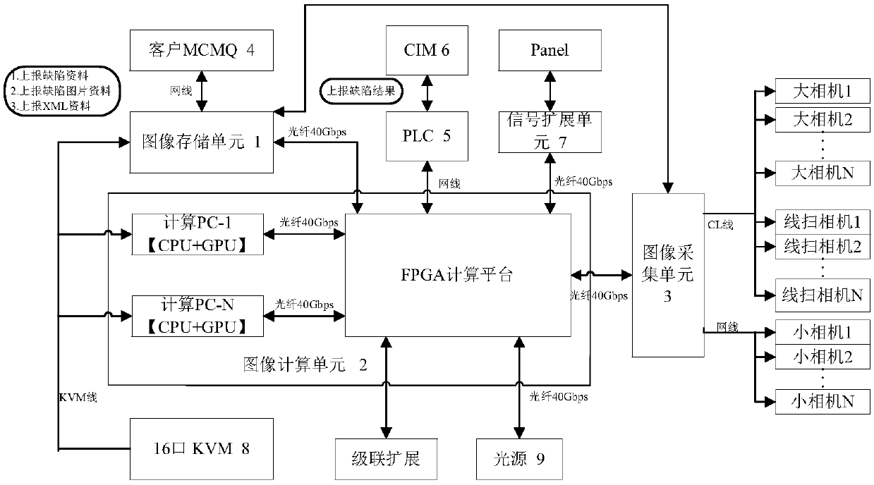
[0064] Such as figure 1 As shown, the present invention includes an image storage unit 1, an image calculation unit 2 and an image acquisition unit 3, the image storage unit 1 has a first communication interface and a second communication interface, and the image calculation unit 2 has a first optical fiber interface , a second optical fiber interface, a third optical fiber interface and a fourth optical fiber interface, the image acquisition unit 3 has a third communication interface and a camera interface;

[0065] The image storage unit 1 performs parameter configuration through human-computer interaction, sends configuration parameters and test commands to the image calculation unit through the first communication interface, r...


PUM


Abstract

The invention discloses an automatic optical detection system based on a CPU+GPU+FPGA architecture. The automatic optical detection system comprises an image storage unit, an image calculation unit and an image acquisition unit, wherein the image storage unit is provided with a first communication interface and a second communication interface, the image calculation unit is provided with a first optical-fiber interface, a second optical-fiber interface, a third optical-fiber interface and a fourth optical-fiber interface, and the image acquisition unit is provided with a third communication interface and a camera interface; and the image calculation unit receives configuration parameters and test orders transmitted by the image storage unit and transmits a test result to the image storageunit by virtue of the first optical-fiber interface, receives data of the image acquisition unit and transmits the configuration parameters and the test orders to the image acquisition unit by virtueof the second optical-fiber interface, controls the generation of a point-screen signal by virtue of the third optical-fiber interface, and controls an IO light source by virtue of the fourth optical-fiber interface. The automatic optical detection system based on the CPU+GPU+FPGA architecture has the advantages of simple structure, low cost, good stability, good coordination capacity, high calculation processing capacity and the like.

Description

technical field [0001] The invention belongs to the technical field of automatic optical detection, and in particular relates to an automatic optical detection system based on CPU+GPU+FPGA architecture. Background technique [0002] AOI automatic optical inspection involves optical system, mechanism control system, point screen control system, software control system, image processing system, etc. Traditional AOI equipment is based on image acquisition card + PC, with many acquisition cards and PCs, high cost, difficult coordination, poor system stability, inconvenient expansion, and difficult to use for large-scale module detection; and each TFT-LCD AOI automatic optical Testing equipment manufacturers only have technology accumulation and research and development capabilities in one or two fields, and basically cannot completely cover all fields. They can only build a complete set of AOI automatic optical testing system through the combination of 2-3 products. The overall...

Claims


Application Information

Patent Timeline
Patent Type & Authority Applications(China)
IPC IPC(8): G01N21/01G01N21/95G05B19/042
CPCG05B19/0428G01N21/01G01N21/95G05B2219/2656G06T1/0014G06T1/20G05B19/042G06T7/0002G06T2207/30168
Inventor 沈亚非欧昌东邓标华汪舟梅林海董文忠唐文天李波
Owner WUHAN JINGCE ELECTRONICS GRP CO LTD
Why Eureka
Try Eureka