Phase Change Material Heat Exchanger

a heat exchanger and phase change technology, applied in indirect heat exchangers, heating types, lighting and heating apparatuses, etc., can solve the problems of high production cost, high power consumption/energy-intensive methods, and inability to meet the needs of objects requiring large amounts of energy, and achieve low noise level, low power drain, and low noise

Active Publication Date: 2008-07-31
MG INNOVATIONS CORP
View PDF35 Cites 14 Cited by
  • Summary
  • Abstract
  • Description
  • Claims
  • Application Information

AI Technical Summary

Benefits of technology

[0025]The compressor driven cooler of cars require that the engine be running when using the compressor. The air is then polluted even if the car is not moving. In accordance with the invention, inside air cooling is possible with low power drain if the engine is off. In closed isolated environments such as submarines or clean rooms, a low noise level is an additional basic requirement, when the fresh air supply is not available. This low noise level can be achieved with the present invention.
[0026]In conventional ventilation, heat recovery devices and coolers have long payback times. In addition to the initial costs, traditional heat recovery ventilators and heat pumps utilising outdoor air cannot operate without additional external energy at temperatures below zero Celsius. Indoor air heat pumps, are again of no use when the outdoor air is warmer than the indoor air. Consequently, such devices will have very short operation periods per year (either in winter or summer, but not through the year). Should it be necessary to use both systems together with an air drier or humidifier, the costs would be even higher. Calculated in terms of the hot zones in the United States and of their average electricity tariffs, the ventilation device of the present invention may have a payback time of less than a year. The excellent seasonal performance factor (SPF) is due to the long period of use each year, i.e. throughout the year in practice, since the apparatus operates both in the winter and in the summer.

Problems solved by technology

Conventional compressor cooling is a highly power consuming / energy demanding method.
The thermoelectric unit based on the Seebeck phenomenon converts heat into electricity, however, it has high production costs, thus becoming inappropriate for objects requiring larger amounts of energy.
Ventilation is important, but often it is impossible to use, for example, in places with polluted air, such as in shops on the street level.
One drawback of PCM storages is caused by their poor heat conductivity.
Heat discharges from the PCM storage constitute a major problem, because further heat cannot be stored unless it has first been discharged.
In recuperative cross-current plate heat exchangers, air currents are not reversed, and hence they cannot interact optimally with a PCM storage nor with a regenerative rotating heat recovery cell.
Also one rotary type regenerative heat exchanger can be used that alternately rotates between two counter (air) flows, thereby substituting for two heat exchanger cells, although efficiency is lower and the construction quite complicated and expensive.
Instead of vortex tube, conventional technology such as a compressor can be used to create a thermal difference, but then the efficiency is lower.
If the vortex tube is used alone, the capacity is typically not economical for cooling / heating large spaces.

Method used


Image

  • Phase Change Material Heat Exchanger
  • Phase Change Material Heat Exchanger
  • Phase Change Material Heat Exchanger

Examples


Embodiment Construction

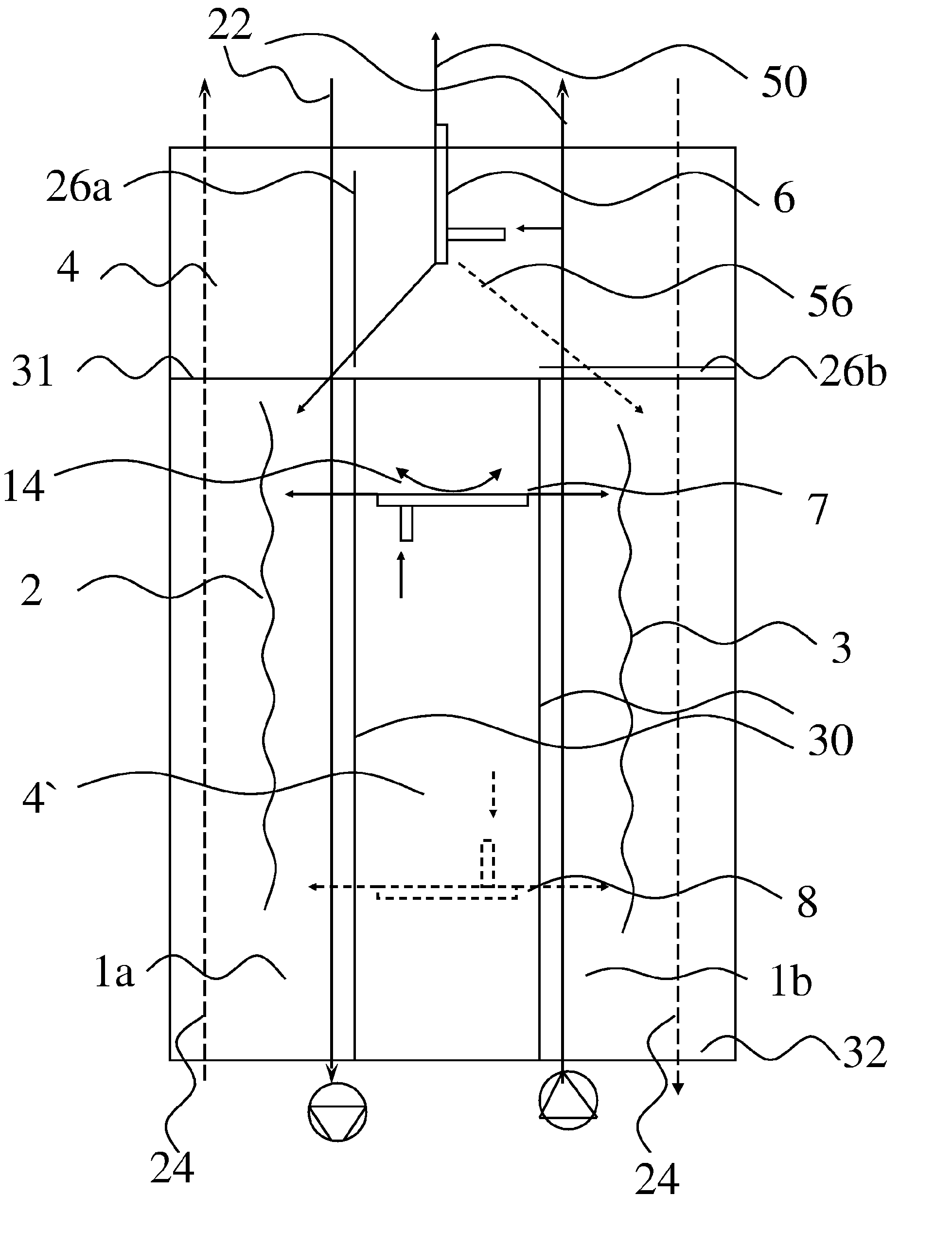
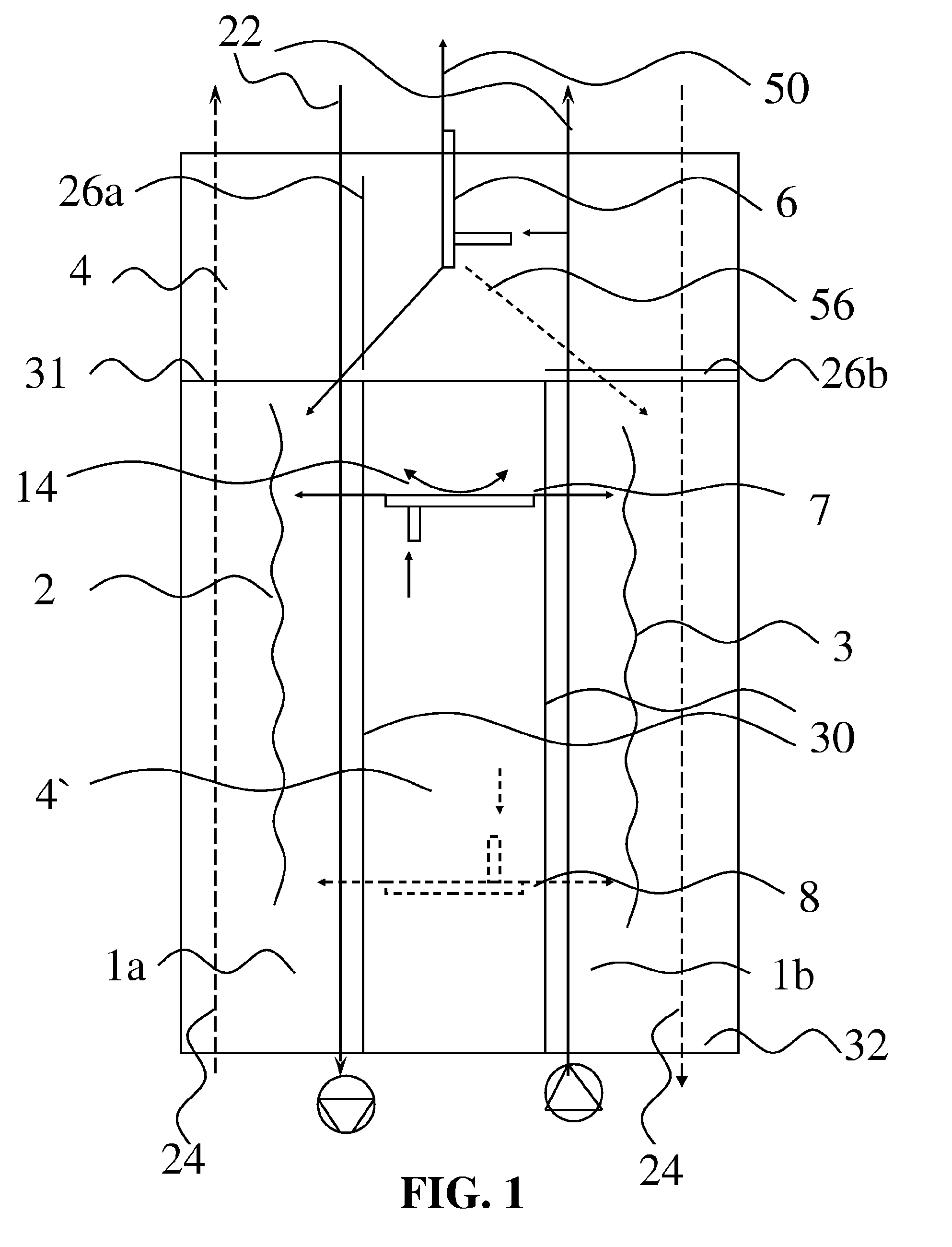
[0030]As seen in FIG. 1, a PCM heat exchanger device according to the present invention comprises at least two regenerative heat exchange cells 1a and 1b operating on the regenerative counter-current principle, through which air, gases or liquids flows are directed to and from the device with alternating and cyclically reversed opposite flow directions. Air flows are shown by arrows 22 and 24. The solid arrows 22 show air flow in one cycle while dashed arrows 24 shows air flow during a second cycle. The change in direction for the air flows in cells 1a and 1b can be performed by known techniques; e.g. diverters, fans, reflectors, flaps, or rotary wheel diverters. These known techniques for changing the air flow direction in the cells 1a and 1b are schematically shown by items 26a and 26b.

[0031]Alternatively, a single rotary type regenerative heat exchanger can be used when modified for two cell air flows, but efficiency is not as good as two heat exchangers.

[0032]The heat exchanger...


PUM


Abstract

The invention relates to a phase change material (PCM) heat exchanger device comprising heat exchanger cells (1a, 1b) operating on the regenerative countercurrent principle, phase change material (PCM) accumulators (2, 3) provided in the heat exchanger cells and a vortex tube (6, 7, 8). When the directions of the air, gas and liquid flows are cyclically reversed in the apparatus, energy is recovered into the heat exchanger cell and the PCM accumulator, and during the subsequent cycle, the energy is released from the heat exchanger cell and PCM accumulator. While one heat exchanger cell and PCM accumulator is being charged, the other heat exchanger cell and PCM accumulator are simultaneously discharged. The cool/hot flow from the vortex tube is used to enhance/create needed temperature differences. The invention is applicable to buildings, vehicles, climate control rooms, single or multiple devices such as computers, and in various processes, such as, but not limited to, cryogenic methods, and in space technology and supercritical carbon dioxide applications.

Description

CROSS REFERENCE TO RELATED APPLICATIONS[0001]This application is the U.S. National Stage of International Application Number PCT / FI06 / 050434 filed on Oct. 10, 2006 which was published in English on Apr. 19, 2007 under International Publication Number WO 2007 / 042621.TECHNICAL FIELD[0002]This invention relates to a heat exchanger comprising a regenerative heat exchanger operating on the counter-current principle and of a phase change material (PCM) enthalpy accumulator in the heat exchanger and / or a vortex tube taking advantage of the Venturi phenomenon. The system provides pre-cooling and pre-drying of fresh ventilation air in the summer and for preheating and pre-moisturising of fresh ventilation air in the winter. The system can be used without ventilation as well. In addition to buildings, the present invention can be used with vehicles, industrial and commercial equipment rooms, as well as any closed compartments which require controlled climatic conditions, for instance for cool...

Claims


Application Information

Patent Timeline
Patent Type & Authority Applications(United States)
IPC IPC(8): F28D17/00F28D15/00
CPCF24F5/0017F24F5/0021F25B9/04F28D17/00F28D20/021Y02E60/14F28D20/02
Inventor MOILALA, KARIGASIK, MICHAEL
Owner MG INNOVATIONS CORP
Why Eureka
Try Eureka