Check patentability & draft patents in minutes with Patsnap Eureka AI!

Electromagnetic pipe expanding inductor and method for manufacturing the same

a technology of inductor and electric pipe, which is applied in the direction of superconducting magnets/coils, magnets, magnetic bodies, etc., can solve the problems of voids, cracks, deformation and breakage, and voids are apt to occur, so as to improve durability remarkably, reduce electromagnetic reaction forces, and diminish shear forces

Inactive Publication Date: 2015-01-06
KOBE STEEL LTD
View PDF6 Cites 5 Cited by
  • Summary
  • Abstract
  • Description
  • Claims
  • Application Information

AI Technical Summary

Benefits of technology

The solution effectively suppresses void formation and enhances the durability of the electromagnetic pipe expanding inductor by reducing shear forces and extending its operational life through improved resin penetration and stress distribution.

Problems solved by technology

However, the above conventional technique involves the following problems.
Consequently, a boundary portion (portion B in FIG. 3) between adjacent glass cloth tape 6 which covers the conductor, the boundary portion being positioned just above the bobbin, is apt to become deficient in impregnation of the resin, with the result that a void is apt to occur.
Therefore, if a void is in the interior of the electromagnetic pipe expanding inductor 101, the void is apt to become a source of developing a crack.
As the electromagnetic pipe expanding inductor 101 is used repeatedly, the crack thus developed becomes larger and is likely to eventually cause deformation and breakage of the electromagnetic pipe expanding inductor 101.
However, under the instantaneous electromagnetic reaction force, there is a fear of pressure breakage or peeling to breakage even of the impregnating resin 22.

Method used


Image

  • Electromagnetic pipe expanding inductor and method for manufacturing the same
  • Electromagnetic pipe expanding inductor and method for manufacturing the same
  • Electromagnetic pipe expanding inductor and method for manufacturing the same

Examples


Embodiment Construction

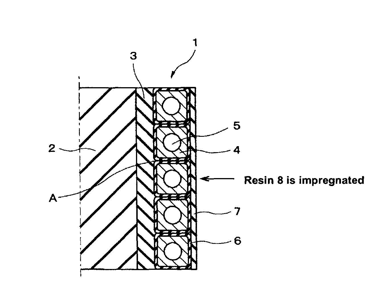
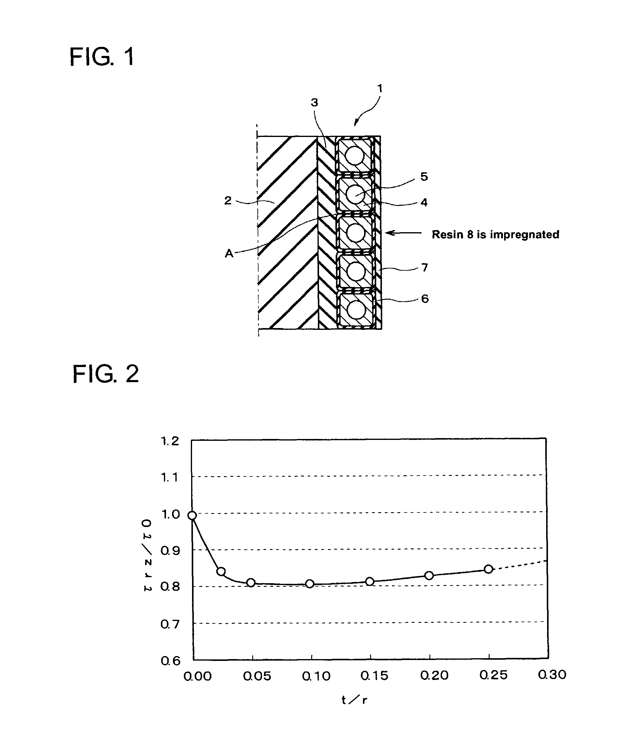
[0027]An embodiment of the present invention will be described below concretely with reference to the accompanying drawings. FIG. 1 is a sectional view showing an electromagnetic pipe expanding inductor according to an embodiment of the present invention. In FIG. 1, one half of the electromagnetic pipe expanding inductor is shown in a section taken along the central axis (indicated by a dot-dash line) of the inductor.

[0028]As shown in FIG. 1, the electromagnetic pipe expanding inductor, indicated by 1, of this embodiment has a columnar bobbin 2 which constitutes a shaft portion. The bobbin 2 is formed of insulating resin for example. The bobbin 2 may have a flange portion or the like for fixing to the exterior, in addition to the shaft portion shown in FIG. 1. Although the bobbin is described herein as being shaft-like, it may be formed in a tubular shape for example.

[0029]Around the peripheral surface of the shaft portion of the bobbin 2 is wound a glass cloth tape 3 to a predeterm...


PUM

PropertyMeasurementUnit
radiusaaaaaaaaaa
thicknessaaaaaaaaaa
thicknessaaaaaaaaaa

Abstract

Provided is an electromagnetic pipe expanding inductor in which the formation of voids during resin impregnation is suppressed, and electromagnetic reaction forces acting on the conductor periphery and on the interface between the shaft portion and the center-side fiber layer is diminished, and thereby durability is improved and the life of the inductor is prolonged. A glass cloth tape (3) capable of being impregnated with resin is wound around the peripheral surface of a shaft portion of a bobbin (2) to a predetermined thickness, further, a conductor strand (4) coated with a glass cloth tape (6) is wound spirally in the axial direction of the bobbin (2) to form a coil. Further, a glass cloth (7) is wound around the outside of the glass cloth tape (6) to a predetermined thickness and thereafter the glass cloth tapes (3, 6) and the glass cloth (7) are impregnated with resin to unite them. A center-side resin-impregnated layer formed by the glass cloth tape 3 impregnated with resin is lower in the modulus of longitudinal elasticity than the shaft portion. Given that the inductor radius is r, the thickness, t, of the center-side resin-impregnated layer is 0.025r to 0.25r.

Description

BACKGROUND OF THE INVENTION[0001]1. Field of the Invention[0002]The present invention relates to an electromagnetic pipe expanding inductor to be used for expanding a metallic pipe or the like which is an electric conductor by utilizing an electromagnetic force, as well as a method for manufacturing the same.[0003]2. Description of the Related Art[0004]According to the electromagnetic pipe expanding technique, an electric charge stored at a high voltage is discharged in an instant to an electromagnetic forming inductor to form a strong magnetic field around the inductor in an extremely short time and a workpiece is disposed within the strong magnetic field, thereby causing an electromagnetic reaction force to be created between the workpiece and a forming coil to expand the workpiece (Patent Literature 1).[0005]The electromagnetic pipe expanding technique permits plastic working of electric conductors (e.g., Al, Cu, non-magnetic stainless steel, Ti) by utilizing an electromagnetic f...

Claims


Application Information

Patent Timeline
Patent Type & Authority Patents(United States)
IPC IPC(8): H01F27/02H01F1/00B21D26/14H01F7/20H01F27/32H01F41/06H01F41/12
CPCH01F27/327B21D26/14H01F27/323H01F41/127H01F7/202H01F27/322H01F41/0687H01F41/122H01F41/098Y10T29/49071
Inventor MORI, MITSUTOSHIHOSOI, HIROAKIKANAHASHI, HIDETAKAIMAMURA, YOSHIHAYA
Owner KOBE STEEL LTD
Features
  • R&D
  • Intellectual Property
  • Life Sciences
  • Materials
  • Tech Scout
  • Unparalleled Data Quality
  • Higher Quality Content
  • 60% Fewer Hallucinations
Learn More