Multiplex electrophoretic display driver circuit

a display driver and electrophoretic technology, applied in the direction of electric digital data processing, instruments, computing, etc., can solve the problems of low frame rate, particularly obvious low frame rate, etc., and achieve the effect of promoting frame refreshing ra

Active Publication Date: 2015-01-06
YUANHAN MATERIALS INC
View PDF8 Cites 126 Cited by
  • Summary
  • Abstract
  • Description
  • Claims
  • Application Information

AI Technical Summary

Benefits of technology

[0004]In the conventional electrophoretic display, a frame for one gray-level matrix signal must be completely refreshed before the next frame for another gray-level matrix signal begins to be refreshed, wherefore the frame refreshing rate may be decreased in facing continuous inputting of the gray-level matrix signals, and wherefore the motion pictures may become sluggish. One objective of the present invention is to provide a driver circuit to improve the problem of motion picture lag.
[0006]The voltage-difference matrix signal is generated via adding the refreshing values to the difference-value matrix signal. The counting circuit utilizes a plurality of counters to perform step counting respectively and generate the refreshing values. Therefore, the difference-value matrix signal and the refreshing values added to the difference-value matrix signal can drive the electrophoretic display to refresh frame by processing multiple gray-level matrix signals simultaneously, whereby the efficiency of frame refreshing rate is promoted.

Problems solved by technology

However, the movement of the charged pigment particles needs a given interval of time to complete.
When the electrophoretic display is used in a touchscreen, the problem of low frame rate is particularly obvious.

Method used


Image

  • Multiplex electrophoretic display driver circuit
  • Multiplex electrophoretic display driver circuit
  • Multiplex electrophoretic display driver circuit

Examples


Embodiment Construction

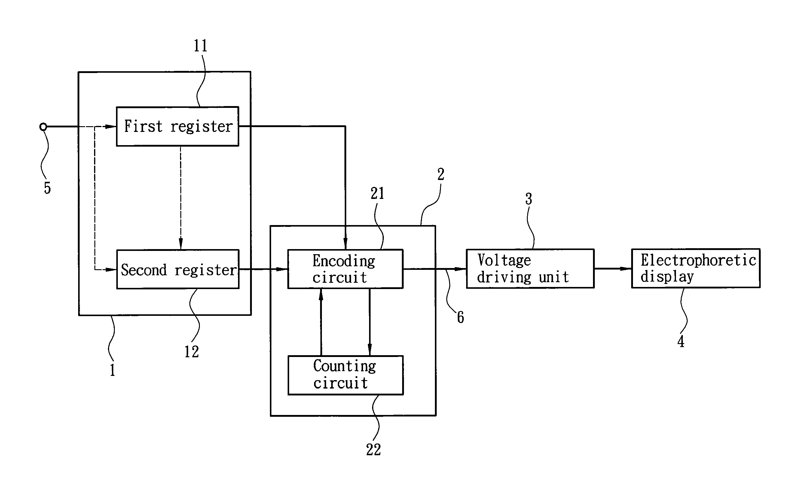
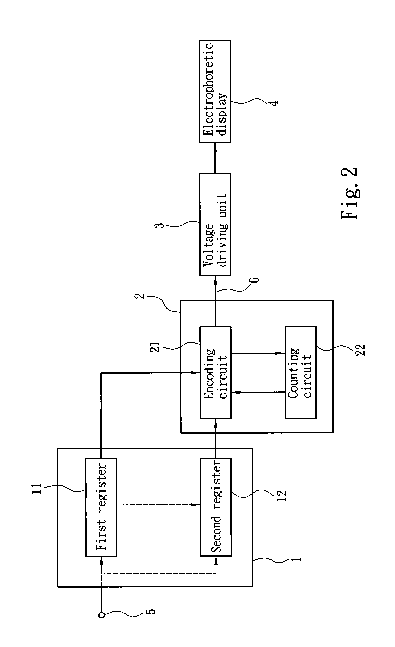
[0010]Refer to FIG. 2. The present invention proposes a multiplex electrophoretic display driver circuit, which comprises a memory unit 1, a display controller 2 and a voltage driving unit 3. The multiplex electrophoretic display driver circuit generates a voltage-difference matrix signal 6 according to a gray-level matrix signal 5. The voltage driving unit 3 utilizes the voltage-difference matrix signal 6 to drive an electrophoretic display 4 having a plurality of electrophoretic pixels 41 (shown in FIGS. 3A-3E). The gray-level matrix signal 5 contains a plurality of gray-level data corresponding to the electrophoretic pixels 41. The voltage-difference matrix signal 6 contains a plurality of voltage-difference data corresponding to the electrophoretic pixels 41. Each of the gray-level data instructs the corresponding electrophoretic pixel 41 to present a gray level between black and white. Each of the voltage-difference data indicates a voltage difference applied to the correspondi...


PUM


Abstract

A multiplex electrophoretic display driver circuit comprises a memory unit, a display controller and a voltage driving unit. The memory unit has two registers respectively storing the current and former gray-level matrix signals. The gray-level matrix signal contains gray-level data corresponding to electrophoretic pixels. The display controller has an encoding circuit and a counting circuit. The encoding circuit generates a difference-value matrix signal containing difference values according to a difference between the current and former gray-level matrix signals and then generates a voltage-difference matrix signal containing voltage-difference signals corresponding to the electrophoretic pixels. The counting circuit receives the difference-value matrix signal and counts to generate refreshing values corresponding to the difference values. The encoding circuit adds the refreshing values to a next-cycled difference-value matrix signal to generate a new voltage-difference matrix signal. The voltage driving unit drives the electrophoretic pixels according to the voltage-difference matrix signal.

Description

FIELD OF THE INVENTION[0001]The present invention relates to a multiplex electrophoretic display driver circuit, particularly to a driver circuit, which uses a counting circuit and at least two registers to process the data series in a multiplex way and accelerate refreshing frames of an electrophoretic display.BACKGROUND OF THE INVENTION[0002]The electrophoretic display (also called the electronic paper or the electronic ink) is distinct from the conventional CRT (Cathode Ray Tube) or LCD (Liquid Crystal Display). In an electrophoretic display, a plurality of micro cups is arranged on a substrate, and each micro cup contains a colored dielectric solvent and charged pigment particles suspending in the colored dielectric solvent. Two electrodes are arranged outside the micro cup. When the two electrodes alter the electric potential drop in the outer rim of the micro cup, the charged pigment particles move toward the electrode charged oppositely. The movement of the charged pigment pa...

Claims


Application Information

Patent Timeline
Patent Type & Authority Patents(United States)
IPC IPC(8): G09G5/00G09G3/30G09G3/34
CPCG09G3/344G09G2340/16
Inventor CHIU, WEN-PINCHENG, PING-YUEHLIN, FENG-SHOULIN, CRAIGCHAN, BRYAN
Owner YUANHAN MATERIALS INC
Why Eureka
Try Eureka